8 Service functio ns and diagnostic messages
80 Festo – GDCP-CMMP-M0-FW-E N – 1304NH
8.2.2 7-segments display
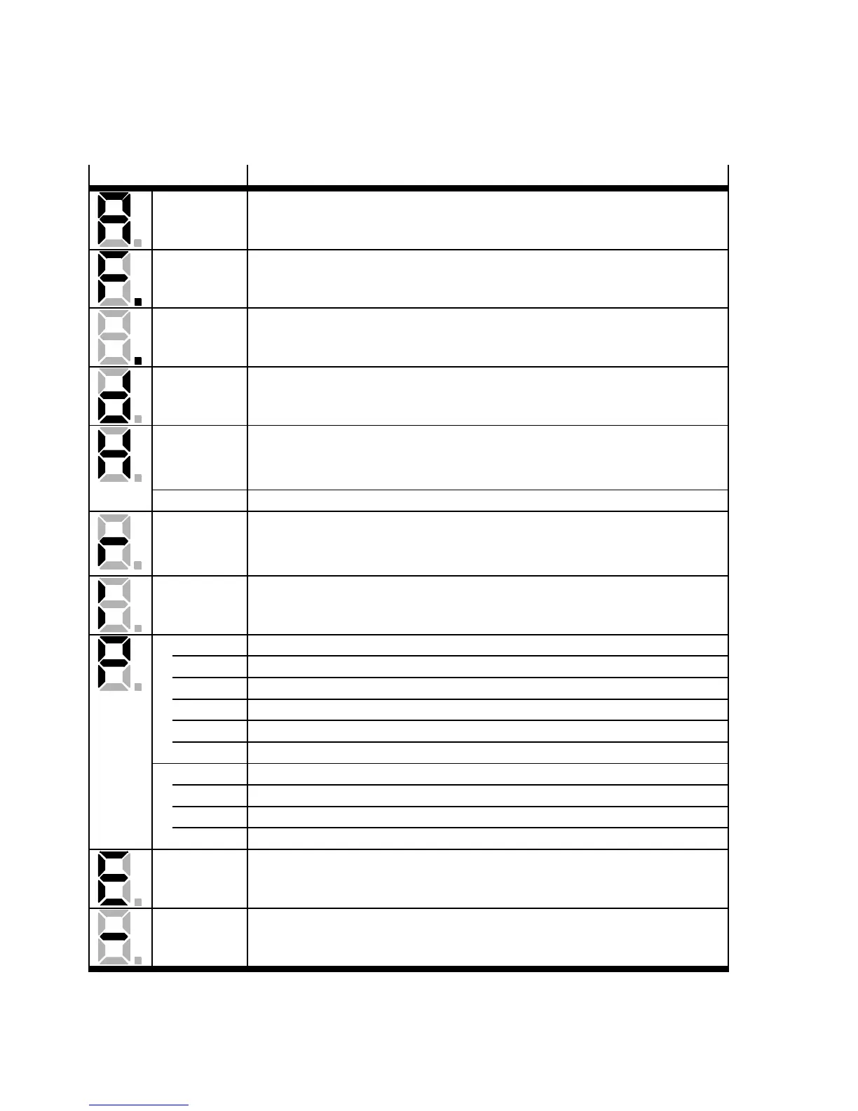
The display and the meaning of the symbols shown are illustrated in the following table:
Display
1)
Significance
A The motor controller must still be parameterised.
F Signals that firmware is c urrently being loaded into the flash.
. (flashes) Bootloader active ( only the point flashes).
d Signals that a parameter se t is currently being loaded from the SD card to
the motor c ontroller.
H(flashes) “H”: The motor controller is in the “safe status”.
This does not have the same meaning as the information on the status of
the safety func tion STO ( Safe Torque Off).
HELLO Display for the function “I dentify Controller”.
(rotating) The outer segments are displayed “rotating” in the speed adjustment
operating mode. The display depends on the actual position or speed. The
middle bar is only active when controller enable is active.
I Controlled torque mode.
Pxxx Positioning (“xxx” stands for the record number, see below).
000 No positioning active.
001...255 Positioning record 001 ... 255 ac tive.
259/260 Jog positive/negative.
262 CAM-IN / CAM-OUT (c am disc).
264/265 Direct records for manual travel via FCT or FHPP direct operation.
PHx Homing (“x” stands for the homing phase, see below).
0 Phase “Search for reference point”.
1 Phase “Crawl”.
2 Phase “Approach zero point”.
Exxy Error message with main index “xx” and sub-index “y”.
-xxy Warning message with main index “xx” and sub-index “y”. A warning is
shown at least twice on the 7-segments display.
1) Several characters are displayed one after the other.
Tab. 8.3 Ope rating mode and error display

 Loading...