6Functions
Festo – GDCP-CMMP-M0-FW-E N – 1304N H 63
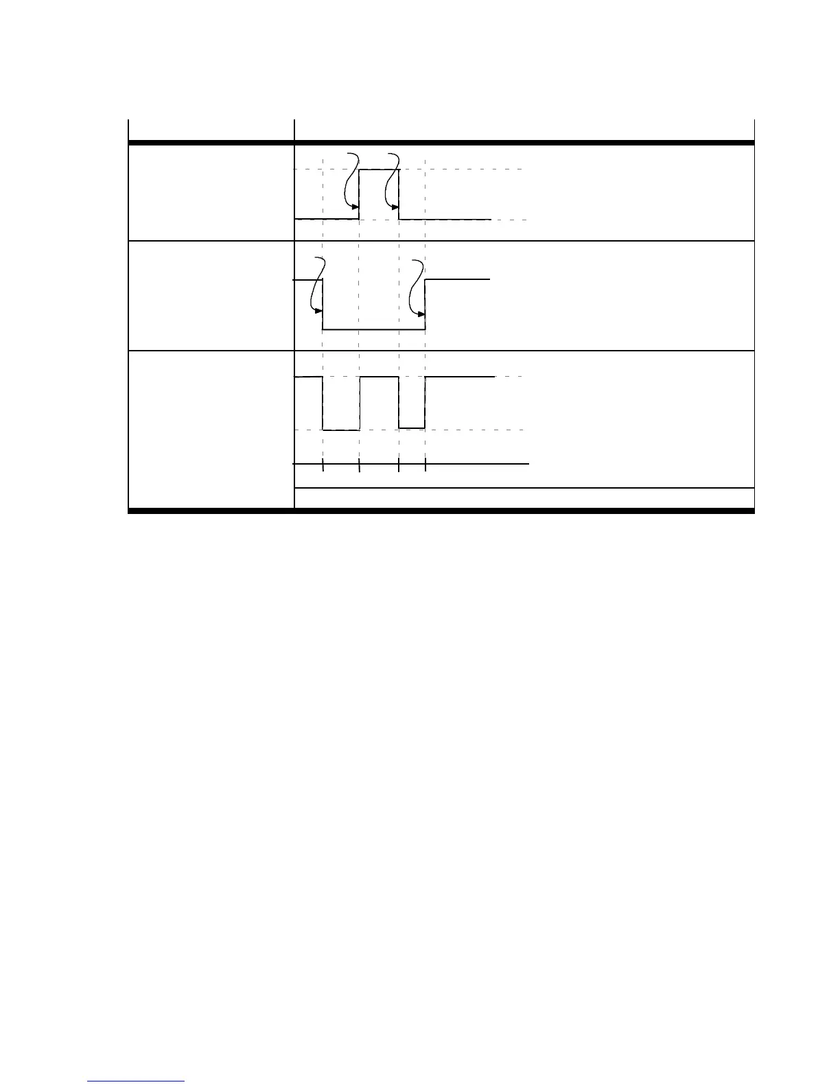
Example Position trigger
Trigger signal switc h 1:
– Position 1 = 400 mm
– Position 2 = 700 mm
1
3
4
0
1
Trigger signal switc h 2:
– Position 1 = 100 mm
– Position 2 = 900 mm
– Signal inverted
1
2
3
4
0
1
Position trigger 1/DOUT:
– Logical O R operation
of the trigger signals
0
1
100 400 700 900
Tab. 6.24 Position trigger
6.7.4 Inputs for option “flying measurement”
The local digital inputs can be used as quick sampling inputs. Setting of the digital input takes place in
the FCT. The inputs DIN8 or DIN9 can be se le cted.
With every rising and falling edge at the configured sample input, the current position value is written
into a register of the motor controller and can afterwards be read out through the higher-order control-
ler ( PLC/IPC). Additional information on the available parameters c an be found in the documentation
for FHPP (GDCP-CMMP-M3/-M0-C-HP-...) or CANopen (G DCP-CMMP-M3/-M0-C-CO-...).
6.7.5 Softwar e limit switch
The permissible positioning range (effective stroke) is limited by setting the software end positions.
The software end positions refer to the axis zero point. If the target position of a positioning command
lies outside of the software limits, the positioning command will not be processed and an error status
will be set.

 Loading...