7 D ynamic response
76 Festo – GDCP-CMMP-M0-FW-E N – 1304NH
7.2 Extended sine modulation for increased output voltage
With the motor c ontroller CMMP-AS-...-M0 the c ycle rate in the current regulator c ircuit is set to a cycle
time of 125μs or 62.5μs. To decrease switching losses, the pulse-width modulation cycle rate can be
set to half the frequency of the current regulator circuit.
The motor controller CMMP-AS-...-M0 also has a sine-wave modulation or, alternatively, an extended
sine-wave modulation (with third harmonic wave). This increases the effective converter output
voltage. The modulation type can be selected using the parameterisation software. The standard set-
ting is extended sine-wave modulation.
7.3 Variable cycle times, current, speed and position controller
The motor controller’s CMMP-AS-...-M0 permit a switchable current c ontrol c ycle time. From these set-
tings are derived the cycle times for the speed and position controller as well as the interpolation time.
Faster c ycle times permit lower reaction times and an improved control dynamic (depending on the
application, higher possible closed-loop gain or lower “ove r shooting” of the position actual values).
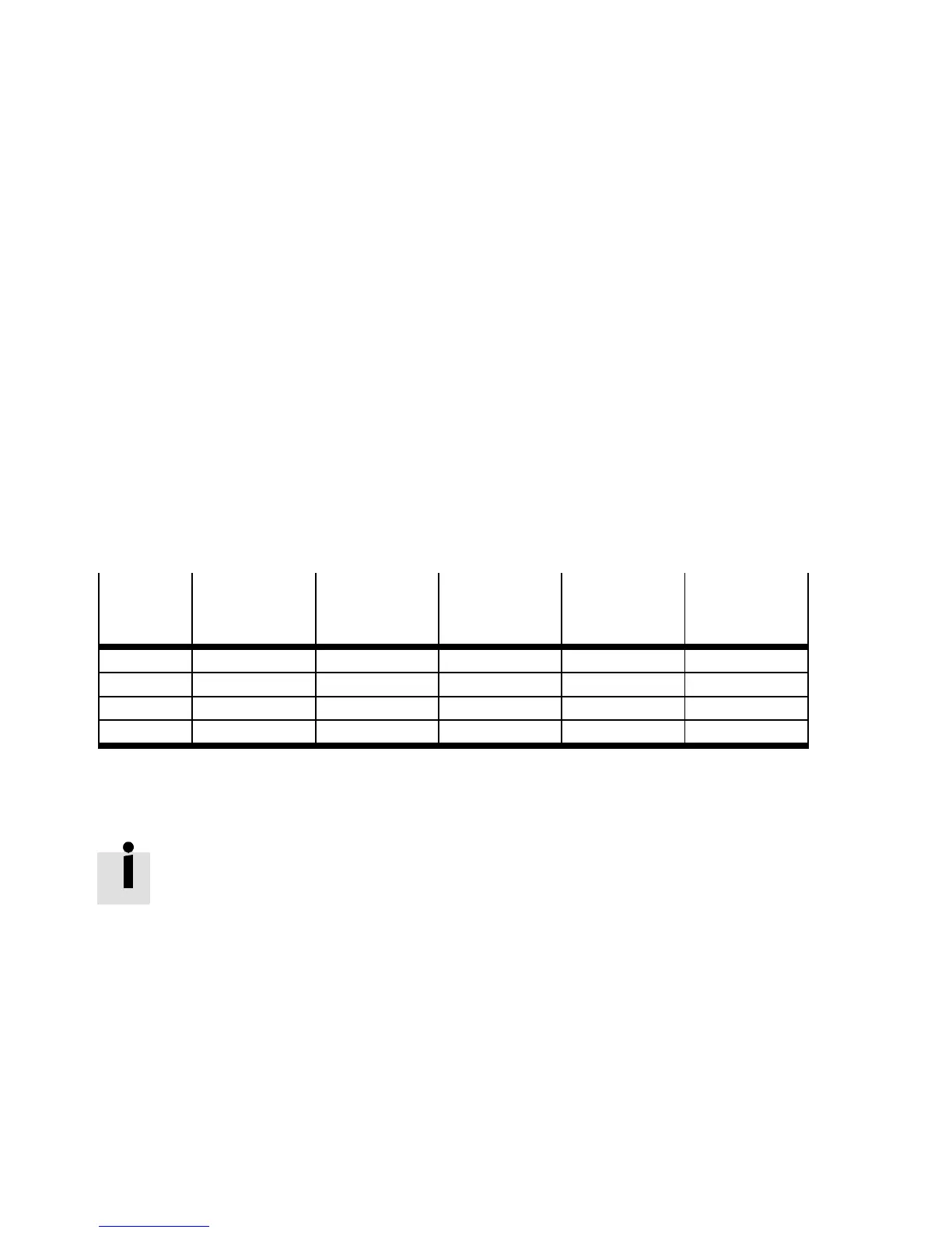
The following table contains the PWM frequencies and related c ycle times that the CMMP-AS -...-M0
supports:
PWM
frequency
Scanning
frequency of
current control
Cycletimeof
current control
Cycle time of
speed
adjustment
Cycletimeof
position
control
Interpolation
time
4kHz 8kHz 125 μs 250 μs 500 μs 1000 μs
8kHz 8kHz 125 μs 250 μs 500 μs 1000 μs
8kHz 16 kHz 62.5 μs 125 μs 250 μs 500 μs
16 kHz 16 kHz 62.5 μs 125 μs 250 μs 500 μs
Tab. 7.1 PWM frequencies and cycle times
The PWM frequency can be set in the parameterisatio n software FCT with the option “Half output sta g e
frequency”.
With higher PWM frequencies, th e result is re duced nominal/pe ak currents of the power
sections. Derating tables Technical data GDCP-CMMP-M0-HW-....

 Loading...