8 Service functio ns and diagnostic messages
Festo – GDCP-CMMP-M0-FW-E N – 1304N H 79
8.1.9 Commis s ioning status
Motor c ontrollers sent to Festo for servicing are loaded with other firmware and parameters for testing
purposes.
Before a new commissioning takes place at the end customer, the motor controller CMMP-AS -...-M0
must be pa ramete rise d. The parameterisat io n software queries the commissioning status and prompts
the user to parameterise the motor controller. In parallel, the device signals through the visual indicat-
or “A” on the 7-segments display that, although it is ready for operation, it has not been parameterised
yet.
8.1.10 Rapid discharge of the intermediate circuit
When a mains supply failure is detecte d, the intermediate circuit is quickly discharged within the saf ety
time specified in E N 60204-1.
Delayed connection of the brake chopper by power class in parallel operation and when a mains failure
occurs ensures that the main energy during rapid discharge of the intermediate circuit is taken over
through the braking resistors of the higher power classes.
But the rapid discharge can be ineffective in certain device constellations, especially
when several motor controllers are connected in parallel in the intermediate circuit or a
brake resistance is not connected. The motor controllers may carry dangerous voltage for
up to 5 minutes after being switched off (capacitor residual c harge).
8.2 Operating mode and error messages
8.2.1 Operating mode and error display
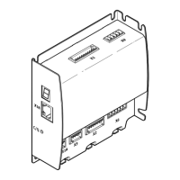
The motor controller CMMP-AS-...-M0 has on the front side three LEDs and a 7-segments display for
display of the opera ting statuses.
Element
LED colour Function
7-segments display – Displays the operating mode and a coded error number in
case of error.
LED1 Green Operating status
Red Error
LED2 Green Controller enable
LED3 Yellow CAN bus status display
R ESET button – Hardware reset for the processor
Tab. 8.2 Display components and RESET pushbutton

 Loading...


