6Functions
Festo – GDCP-CMMP-M0-FW-E N – 1304N H 65
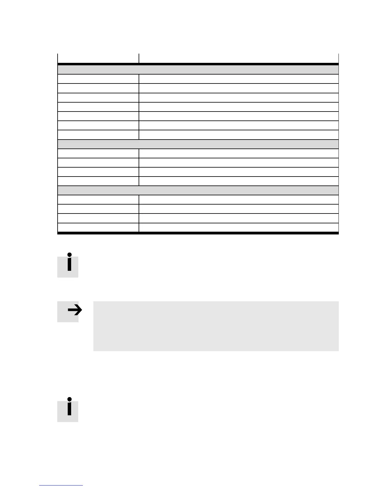
Digital I/O Function
Standard DI N
DI N 0…DI N3 CAN node number; configurable
DI N 4 Fix: Output stage enable (POWER ENABLE)
DI N 5 Fix: Controller enable (CONTROLLER ENABLE)
DI N 6 Fix: Limit switch negative (LI MIT 0)
DI N 7 Fix: Limit switch positive ( LIM IT 1)
DI N 8 Activation of CAN bus; configurable
DI N 9 Shift of CAN communication profile (CiA 402 or FHPP); configurable
Standard DOUT
DOUT0 Fix: Motor controller ready for operation (READY)
DOUT1 Configurable
DOUT2 Configurable (optional: DIN10)
DOUT3 Configurable (optional: DIN11)
Additional DIN
DI N10 (DOUT2) Configurable
DI N11 (DOUT3) Configurable
DIN12 (AIN1) C AN bit rate (in combination with DI N13); c onfigurable
DIN13 (AIN2) C AN bit rate (in combination with DI N12); c onfigurable
Tab. 6.26 Assignment DIN/DOUT
Activated signal inputs require calculation time of the motor controller.
Therefore, do not deactivate required signal inputs.
Functions of the digital inputs
Note
Multiple assignments of digital inputs are tolerated by the firmware.
Execution of the function with multiple assignment depends on the respectively set
operating mode.
• Check carefully whether your c ombination of input signals makes sense.
Function assignment is dependent on:
– the control interface used
– the selected operating mode
– the number of freely usable inputs.
To control additional functions via digital inputs, you c an change the factory-set
assignment of the digital inputs present at the basic unit .

 Loading...