1. Installation
1−4
Festo P.BE−CPX−FB13−EN en 0811c
Electrical connection and display elements
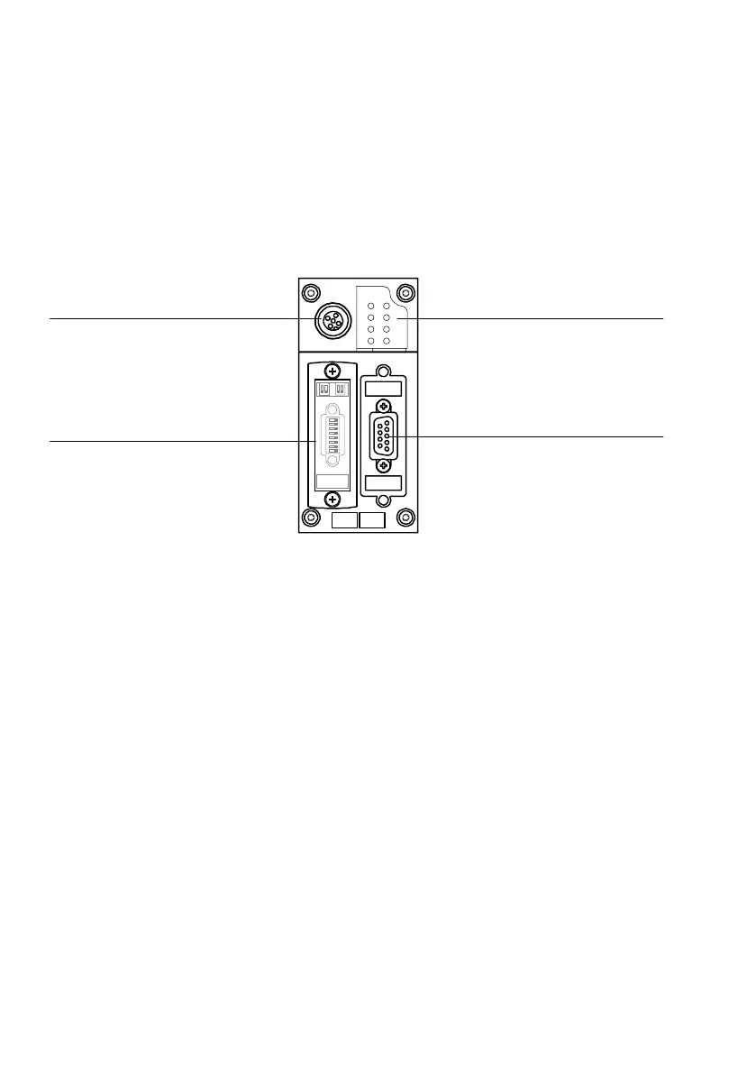
You will find the following electrical connection and display
elements on the CPX field bus node for PROFIBUS−DP:
BF PS
PL
SF
M
1
2
3
4
1 Bus−status−specific and
CPX−specific LEDs
2 Field bus connection
(9−pin sub−D socket)
3 Transparent cover for the DIL switches
4 Service interface for handheld (V24)
und USB adapter (for CPX−FMT)
Fig.1/1: Connecting and display elements on the CPX field bus node