2. Commissioning
2−14
Festo P.BE−CPX−FB13−EN en 0811c
Configuration examples
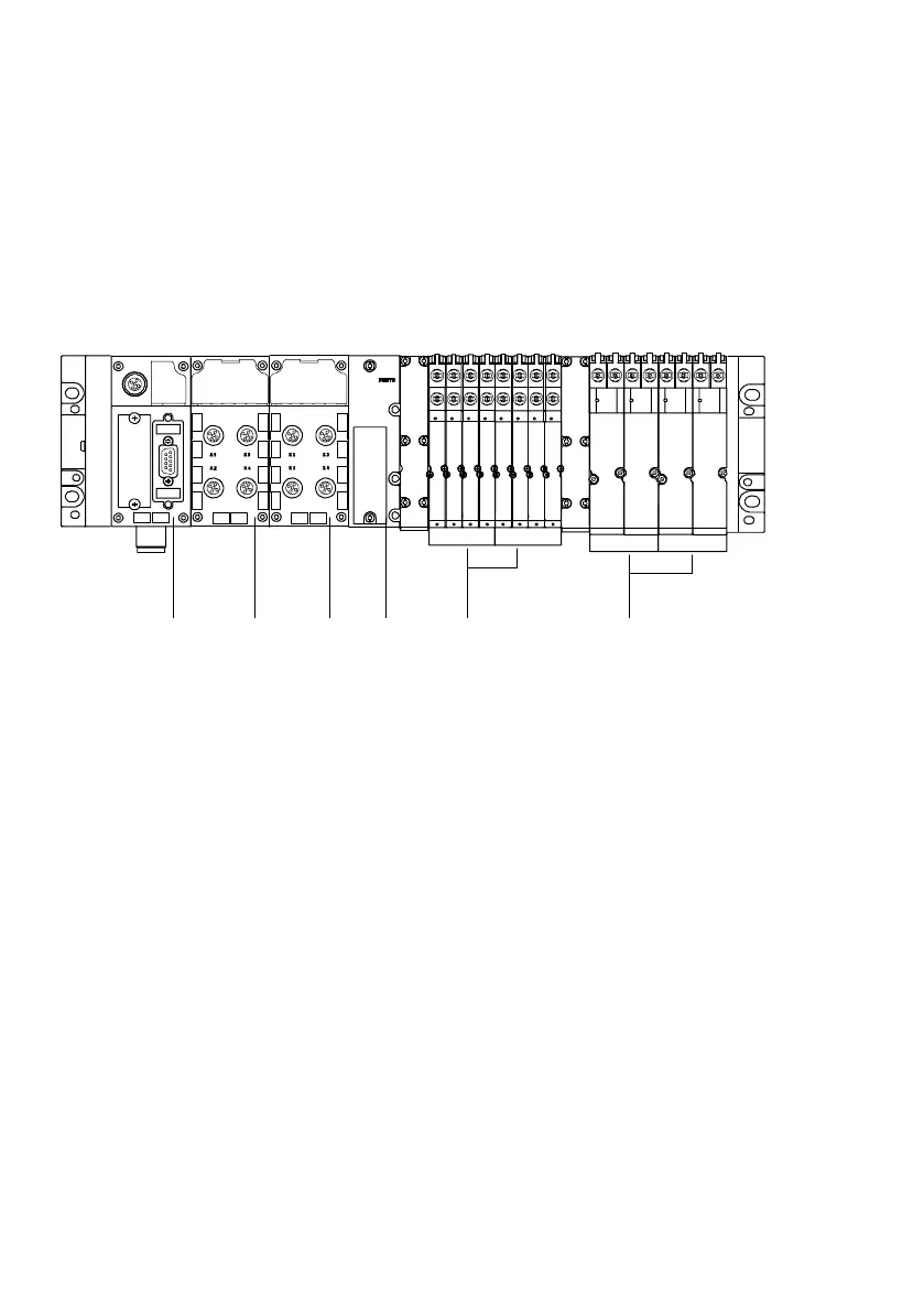
Example 1: CPX valve terminal with MPA pneumatics
8DI 4DO
8 O
0
12 34
1234 5 6
5Module no.:
6
8 O
4 O4 O
1 Field bus node CPX−FB13
2 8−input module
3 4−output module
4 Pneumatic interface
for MPA pneumatics
5 Valves/MPA1 pneumatic modules
6 Valves/MPA2 pneumatic modules
Fig.2/2: Example terminal 1 (with MPA1 and MPA2 pneumatics)
Configure the CPX terminal module−by−module from left to
right. The following table shows the configuration of the
above terminal example: