2. Commissioning
2−19
Festo P.BE−CPX−FB13−EN en 0811c
In the example, the CP interface occupies 4 input bytes and
16 output bytes (see manual for CPX−CP interface, chapter
System overview of CP system").
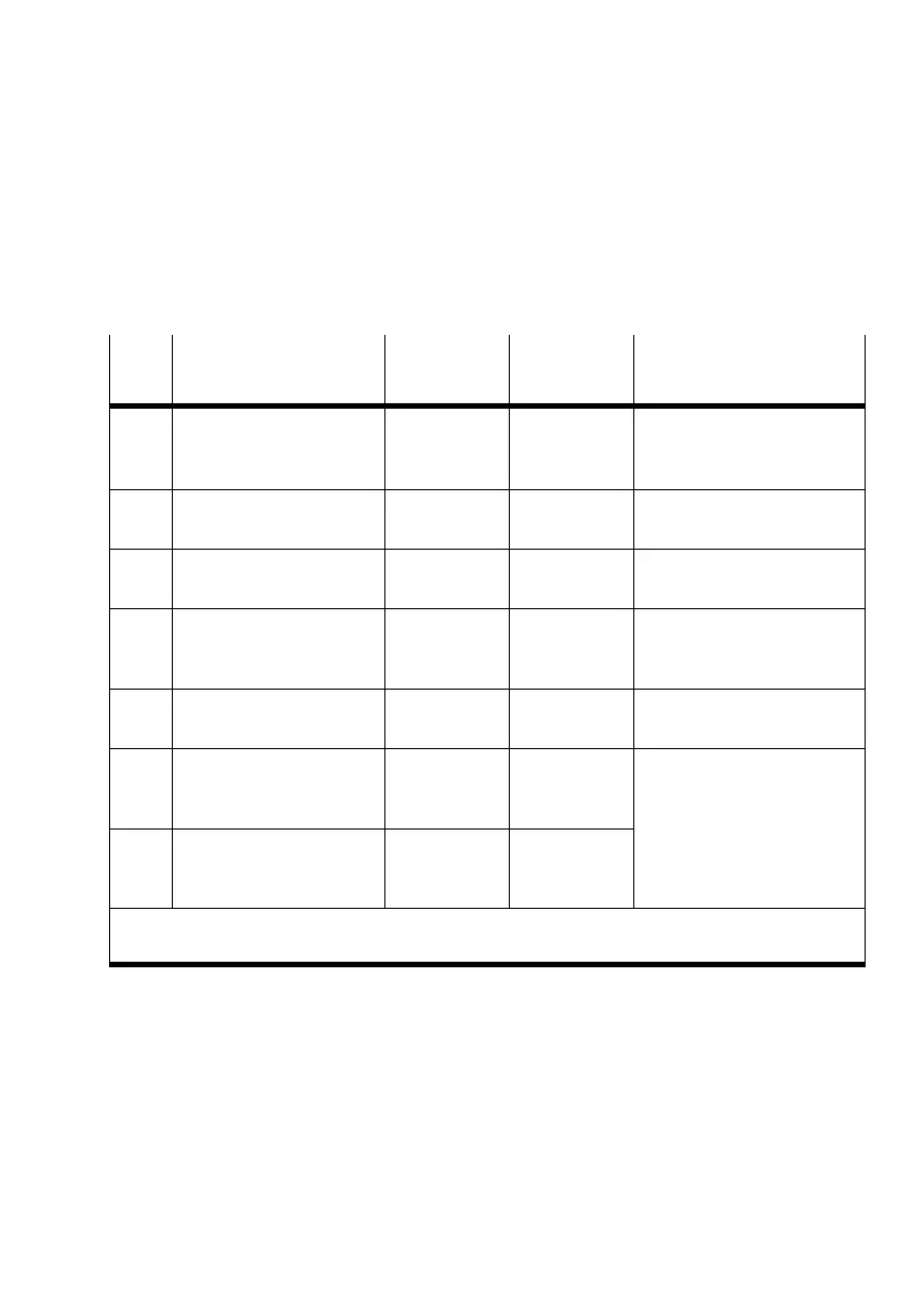
Mod.
no.
Module
Siemens order number
DP identifier
Siemens
DP identifier
EN 50170
Explanation
0 Field bus node
CPX−FB13: DP slave
[status]
64
d
40
h
, 00
h
Configured with status bits
1 Digital 8−input module
CPX−8DE [8DI]
8DI 10
h
Identifier byte used
completely
2 Digital 4−output module
CPX−4DA [4DO]x2
8DO 20
h
Only the first 4 bits of the
identifier byte are used
1)
3 CP interface
CPI:4 bytes I/16 bytes O
192 C0
h
, 0F
h
, 03
h
CP interface with assignment
of 4 input bytes and
16output bytes
4 Digital multi I/O module
CPX−8DE−8DA [8DI/8DO]
8DX 30
h
Identifier byte used
completely
5 MPA1 pneumatic module
MPA1S: VMPA1−FB−EMS−8
[8DO]
8DO 20
h
MPA1 pneumatic modules
without separate power
supply circuits.
Identifier bytes are used
6 MPA1 pneumatic module
MPA1S: VMPA1−FB−EMS−8
[8DO]
8DO 20
h
Identifier bytes are used
completely.
1)
As no output module with groupable identifier is used in the subsequent locations,
8 bits are assigned here, but only 4 are used.
Tab.2/12: Configuration for example terminal 3