16 MS-9050 Series Manual — P/N 52413:F 10/22/2010
Product Description Circuits
LED Indicators
LED indicators are provided to annunciate the following conditions:
• AC Power (green)
• Fire Alarm (red)
• Supervisory (yellow)
• Trouble (yellow)
• Alarm Silenced signals (yellow)
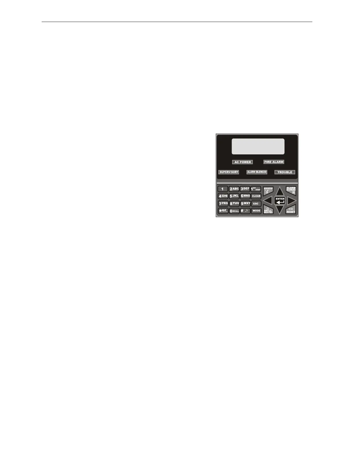
Key Panel
Mounted on the main circuit board, the key panel includes a window for the LCD display and LED
indicators as listed above. The key panel, which is visible with the cabinet door closed, has 25
keys, including a 16 key alpha-numeric pad similar to a telephone keypad.
Function keys:
• Acknowledge/Step
• Alarm Silenced
• Drill (Manual Evacuate)
• Reset (lamp test)
Service/program keys:
• Keys labeled 1 to 9
• * key
• # key
• 0 (recall) key
• 1st Event key
• Clear key
• Escape key
• Mode key
• Four cursor keys (up, down, left and right)
• Enter key
Local Piezo Sounder
A piezo sounder provides separate and distinct pulse rates for alarm, trouble and supervisory condi-
tions.
1.4 Circuits
SLC Communication Loop
One SLC loop is provided on the FACP main circuit board. The SLC loop, configurable for NFPA
Style 4, 6 or 7, provides communication to addressable detectors, monitor (initiating device) and
control (output device) modules. Refer to the SLC Wiring manual for information on wiring
devices.
Output Circuits
The following output circuits are available on the FACP:
• Charger - 24 VDC Battery Charger (up to 18 AH batteries)
• NAC (Notification Appliance Circuits) - Two NACs configurable for Style Y (Class B) or
Style Z (Class A), are provided with various programmable features.
Figure 1.2 Membrane/Display Panel
9050udkypd.cdr