MS-9050 Series Manual — P/N 52413:F 10/22/2010 49
ANN-BUS Devices Installation
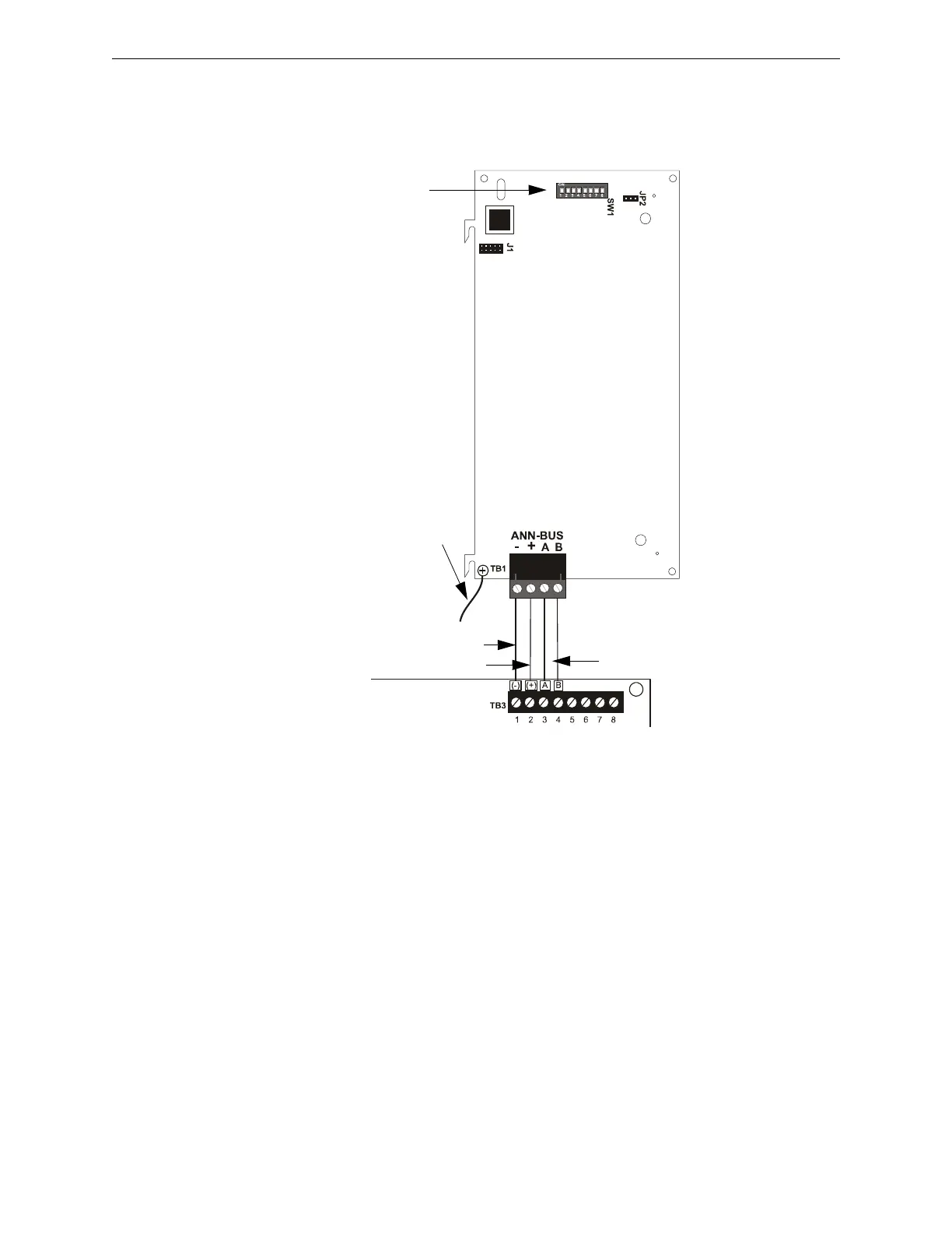
ANN-LED Board Layout and Connection to FACP
Figure 2.22 illustrates the ANN-LED board showing locations of screw terminals for connection to
the FACP and the DIP switches for selecting the ANN-BUS ID number.
2.9.7 ANN-RLY Relay Module
The ANN-RLY relay module provides 10 programmable Form-C relays when used with a compat-
ible FACP.
Specifications
• Operating Voltage: 24 VDC
• Max. Current:
Alarm: 75 mA
Standby: 15 mA
• Operating Temperature: 32
o
F to 120
o
F (0
o
C to 49
o
C)
• For indoor use in a dry location only
Figure 2.22 ANN-LED Connection to FACP
ANN-LED
+24 VDC
-24 VDC
ANN-BUS and power wiring are
supervised and power-limited
MS-9050UD
Primary ANN-BUS
Ground wire from mounting screw to
FACP Earth Ground stud is required
for some Canadian applications.
(Refer to “ANN-LED Annunciator
Installation for Canadian
Applications” on page 208).
ANN-BUS (ID#)
Address DIP switch
annledto9050ud.wmf