MS-9050 Series Manual — P/N 52413:F 10/22/2010 31
UL Power-limited Wiring Requirements Installation
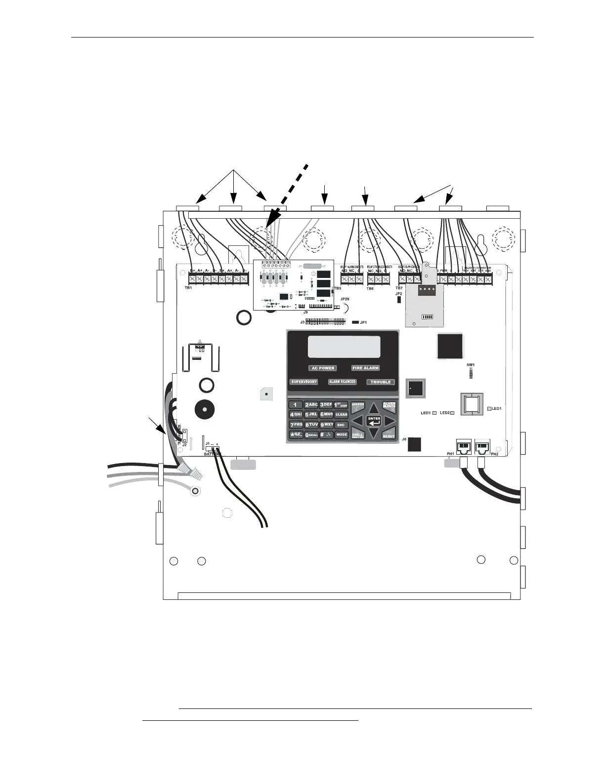
2.6 UL Power-limited Wiring Requirements
Power-limited and nonpower-limited circuit wiring must remain separated in the cabinet. All
power-limited circuit wiring must remain at least 0.25” (6.35 mm) away from any nonpower-lim-
ited circuit wiring and nonpower-limited circuit wiring must enter and exit the cabinet through dif-
ferent knockouts and/or conduits. A typical wiring diagram for the FACP is shown below.
2.7 Digital Communicator
Two independent telephone lines can be connected to the control panel. Telephone line con-
trol/command is made possible via double line seizure as well as usage of an RJ31X style intercon-
nection. Note that it is critical that the panel's digital communicator be located as the first device
on the incoming telephone circuit to properly function.
Figure 2.7 Typical UL Power-limited Wiring Requirements
Power-limited Circuits (Class 2)
Power-limited
Circuits (Class 2)
Nonpower-limited Circuits (Class 1)
Nonpower-limited,
(Class 1)
supervised
Telephone Circuit
AC Power
Hot
Neutral
Ground
9050udulpwr2.wmf
To Batteries
(nonpower-limited, Class 1
supervised)
maintain minimum 0.25” between power-
limited and nonpower-limited circuits wiring
Ground Stud
Transformer Wires
(nonpower-limited,
supervised)
4XTMF
ANN-SEC