40 MS-9050 Series Manual — P/N 52413:F 10/22/2010
Installation ANN-BUS Devices
2.9.2 ANN-BUS Device Addressing
Each ANN-BUS device requires a unique address (ID Number) in order to communicate with the
FACP. A 5-position DIP switch on each device is used to set this address. The address set for these
devices must also be programmed at the FACP for the specific device (refer to the programming
section titled “ANN-BUS” on page 108).
A maximum of 8 devices can be connected to the FACP ANN-BUS communication circuit. Device
addresses do not need to be sequential and can be set to any number between 01 and 08. Note that
00 is not a valid address. The following table shows the DIP switch setting for each address.
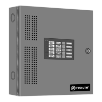
2.9.3 ANN-80(C) Remote Fire Annunciator/Indicator
The ANN-80(C) Annunciator/Indicator is a compact, 80 character, backlit LCD remote fire annun-
ciator which mimics the FACP display. It also provides system status indicators for AC Power,
Alarm, Trouble, Supervisory and Alarm Silenced conditions. The ANN-80 Annunciator provides a
button for Reset, Silence, Acknowledge, and Drill. The ANN-80C does not provide these buttons.
Communication between the ANN-80(C) and FACP is accomplished over a two wire serial inter-
face employing the ANN-BUS communication format. The devices are powered, via two addi-
tional wires, from either the host FACP or remote UL-listed, filtered, power supply.
Specifications
• Operating Voltage Range: 18 VDC to 28 VDC
• Current Consumption @ 24 VDC nominal (filtered and nonresettable):
Normal/Standby (no activity): 37.0 mA
Trouble: 39.0 mA
Alarm: 40.0 mA
AC Fail ( not backlit): 15.0 mA
• For use indoors in a dry location
Installation
Ensure that all power (AC and DC) has been removed from the FACP before installing the annunci-
ator.
Opening/Closing Annunciator
The following procedure details the steps used to open the annunciator in order to access the termi-
nal block and DIP switches (refer to figure below):
1. Turn the key switch to the ON (Unlocked) position by turning the key counter-clockwise
2. Push in the snap latch located on the right side of the unit while pulling the cover open
Address
Switch 5
1
1 Switch 5 must be set to OFF for ANN-BUS devices to be recognized.
Switch 4 Switch 3 Switch 2 Switch 1
not valid OFF OFF OFF OFF OFF
01 OFF OFF OFF OFF ON
02 OFF OFF OFF ON OFF
03 OFF OFF OFF ON ON
04 OFF OFF ON OFF OFF
05 OFF OFF ON OFF ON
06 OFF OFF ON ON OFF
07 OFF OFF ON ON ON
08 OFF ON OFF OFF OFF