MS-9050 Series Manual — P/N 52413:F 10/22/2010 39
ANN-BUS Devices Installation
Wiring Configuration
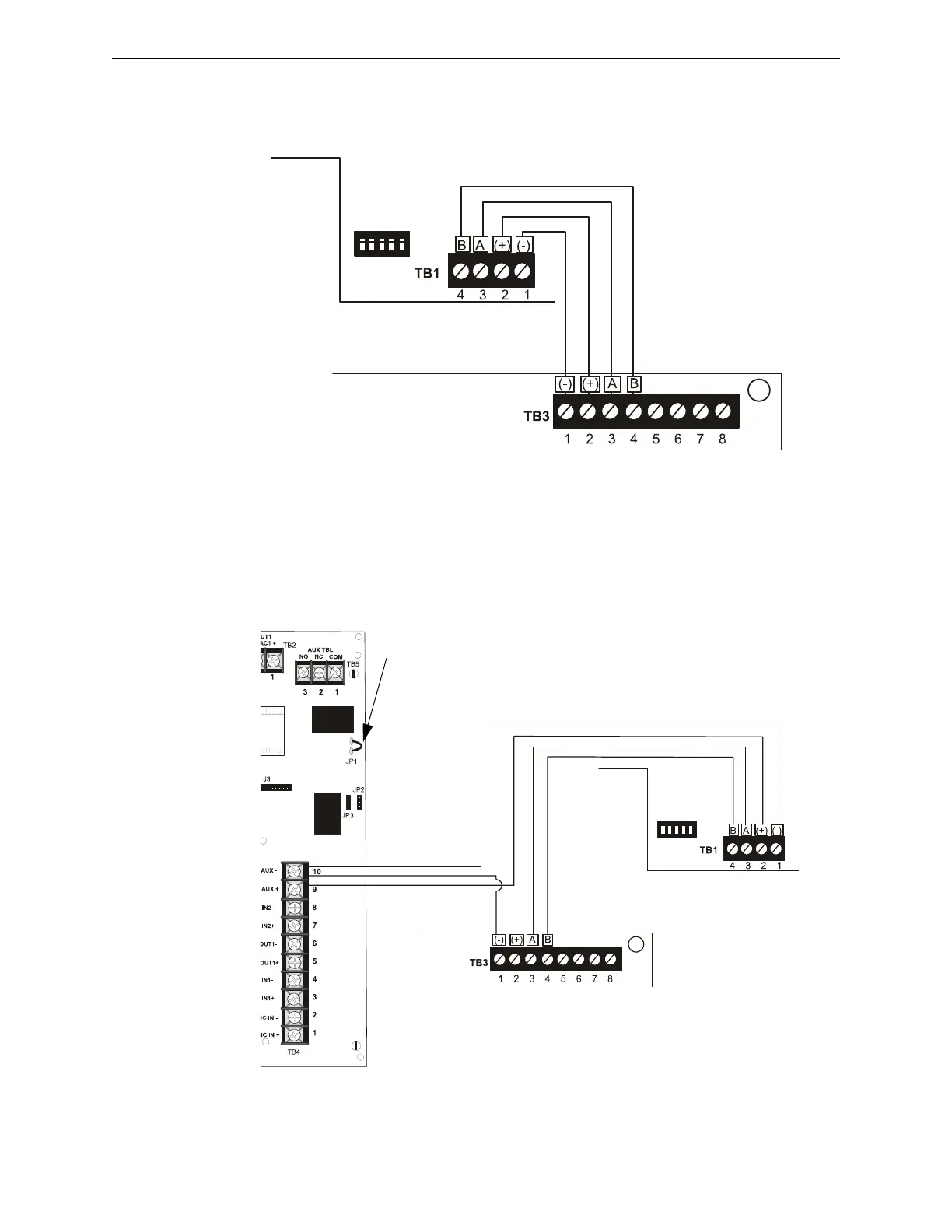
Figure 2.13 illustrates the wiring between the FACP and ANN-BUS devices.
Powering ANN-BUS Devices from Auxiliary Power Supply
Figure 2.14 illustrates the powering of ANN-BUS devices from an auxiliary power supply such as
the FCPS-24FS6/8, when the maximum number of ANN-BUS devices exceeds the ANN-BUS
power requirements.
Figure 2.13 FACP wiring to ANN-BUS Device
ANN-BUS Device
MS-9050UD
ANN-BUS and power wiring are
supervised and power-limited
Primary ANN-BUS
Figure 2.14 Powering ANN-BUS Devices from FCPS-24FS6/8
ANN-80
MS-9050UD
FCPS-24FS6/8
-24 VDC
+24 VDC
ANN-BUS
Cut Ground Fault Detection jumper JP1 (FACP monitors for ground faults)
ANN-BUS and power wiring are
supervised and power-limited
ann80tofcps.wmf