478182
23
4.9.8 Testing the Pump Stator
SmartPump™ Wiring Diagram
The stator resistance can either be tested from the harness at the motor controller or at the
connections to the stator itself.
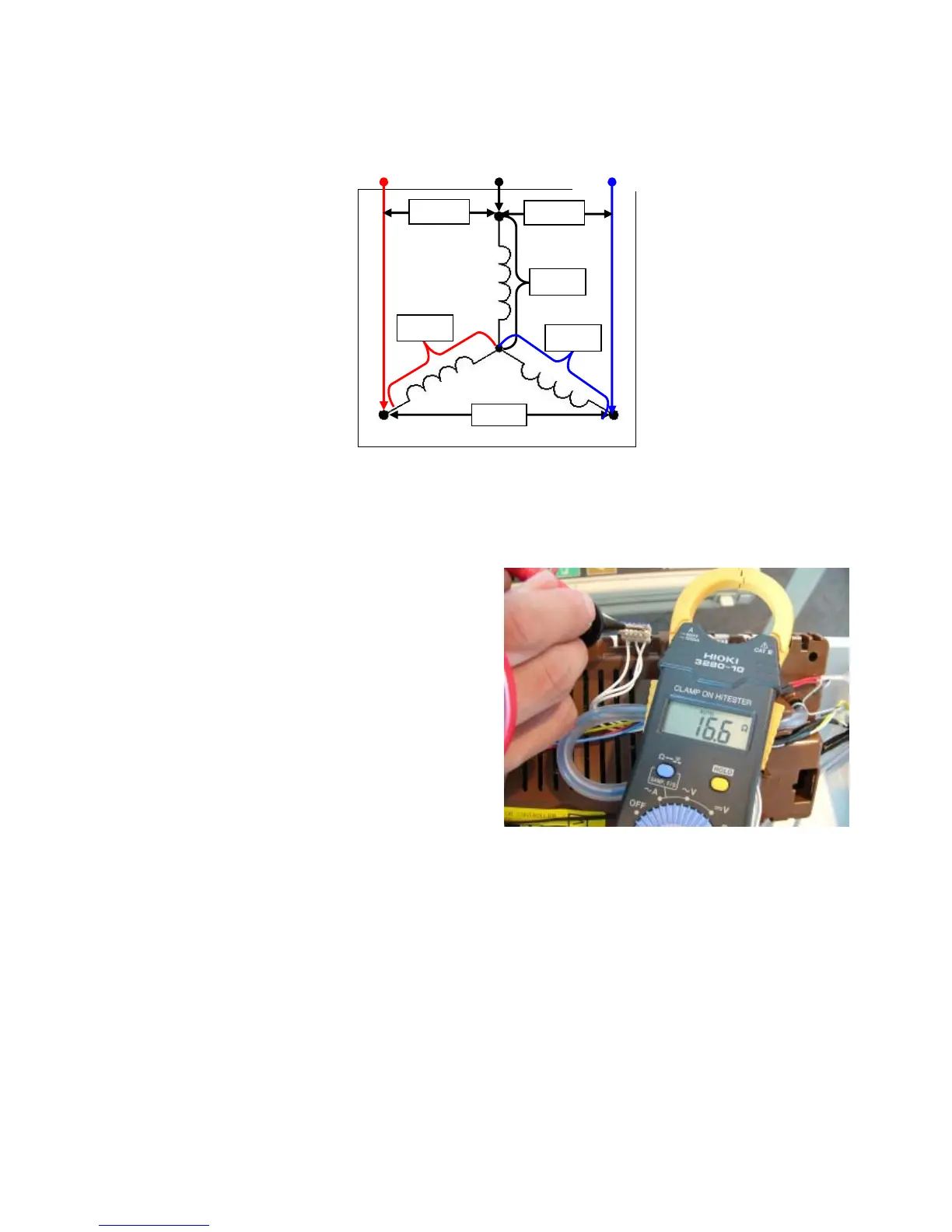
4.9.9 Testing SmartPump™ Stator from the Console
The resistance of each individual winding is
approximately 8.1Ω +/- 10%, however when
testing the stator from the console we are
testing across two windings, therefore the
resistance should be approximately 16.2Ω +/-
10%.
To test all windings you will need to measure
across:
• Red and White
• White and Blue
• Blue and Red
If the meter shows an incorrect reading, we would recommend testing the stator from underneath
the machine, as there could be a fault in the wiring harness. To test the stator it will need to be
removed from the machine (refer to Section
10.19).
BLUE
RED
WHITE
 Loading...