DC100 MAX Digital Dispenser Operating Manual
© 2023 Fisnar - 64 - DC100 MAX Rev 4
Input Type: Photocoupler
Input Power: Pin #3, 4, 16, 18, 19, 20, 21 and #25 are an externally driven dry-contact voltage free
contact closure circuit (I.E. Switch or Relay).
Input Function (pin #3, 4, 16, 18, 19, 20, 21 and #25):
To activate an input signal, pull the input pin (pin #3, 4, 16, 18, 19, 20, 21 or #25) down to a GND
pin (pin #2, 5, 7, 11, 13, 15 & 17). Input signals utilize the machine internal power supply.
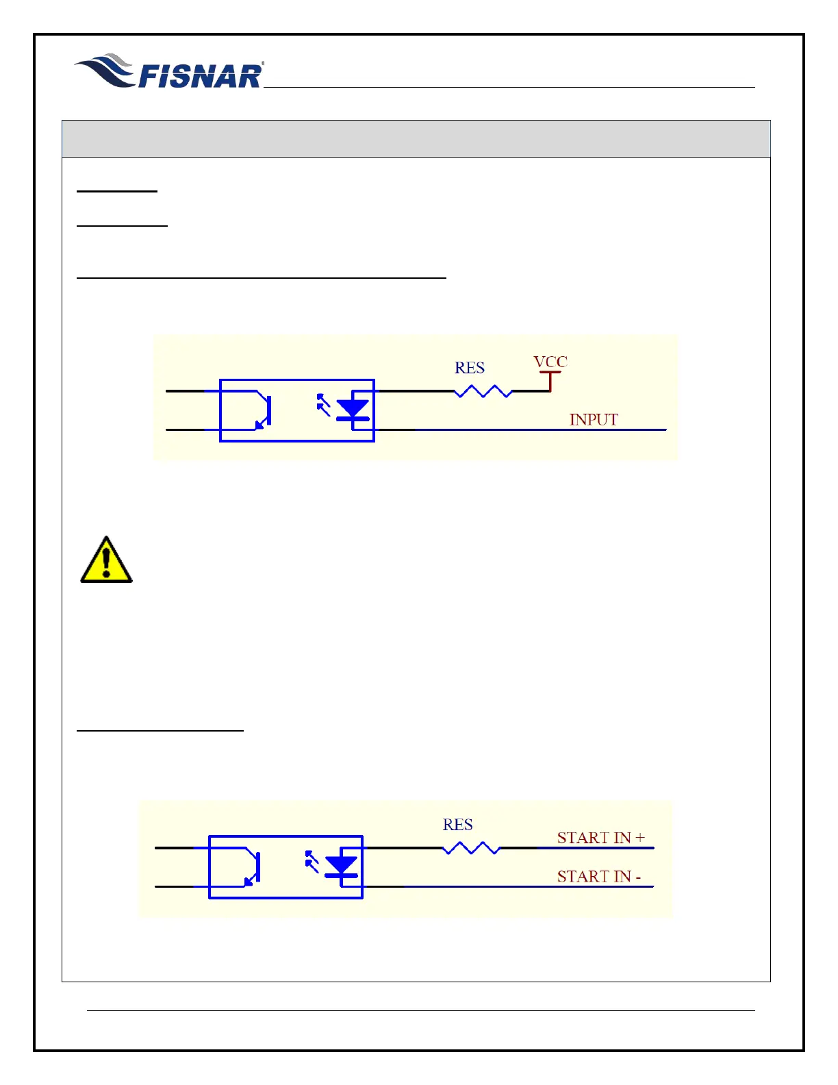
Example of I/O input port driving
PLEASE READ:
A dry contact closure between inputs (pin #3 or pin #4) and any ground will trigger an
input signal. DO NOT apply a voltage to input pin #3 or pin #4 and ground. Doing so
will damage the internal control board and void all warranty conditions.
Input Function (pin #8):
To actuate the machine from an external device using a voltage signal (24V+),
- connect input pin “Start Signal IN 24V+” (pin #8) to an external power supply (24V+)
- connect input pin “Start IN GND (0V)” (pin #9) to an external ground (0V)
Example of I/O input port driving (pin #8)