ST51A/ST75A/ST75AV Mass Flow Meters INSTALLATION
Fluid Components International LLC 5
2 INSTALLATION
The ambient temperature range and applicable temperature class of the ST51A and ST75A/ST75AV Series flow
meters are based on the maximum process temperature for the particular application as follows; T6 for -40 °C ≤ Ta ≤
+55 °C; T3 for -40 °C ≤ Ta ≤ +65 °C.
Instrument Identification and Outline Dimensions
Appendix A provides outline dimensions and mounting bracket dimensions for all integral and remote mounted electronic configurations.
Verify all dimensions meet the application requirements before beginning installation.
Pre-Installation
Serial Number
The ST51A, ST75A and ST75AV (Vortab) flow meters can be specified with integral or remote electronics. The flow element has a serial
number etched into the side of the extension pipe (ST51A) or HEX (ST75A/ST75AV) as shown in Figure 1 below. The tag on the enclosure
includes serial number and model number. A serial number is written on the transmitter’s PWB silkscreen (both AC and DC input) as
shown in Figure 2. The flow sensor and transmitter circuit are calibrated as a matched set. Always pair these components together unless
an exception is made by an FCI technician.
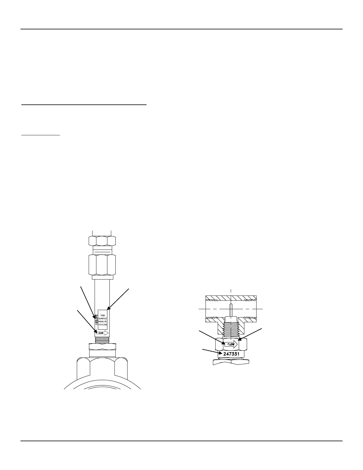
Flow Direction Alignment
All sensor elements have a flow arrow indicator marked on the element assembly at the reference flat, which indicates the flow direction for
which the flow element has been calibrated. Install the instrument with the flow arrow facing in the same direction as flow in the pipe
stream as shown in Figure 3 and Figure 4. The ST75A/ST75AV flow element has been calibrated directly in the pipe tee or tube tee for
orientation and insertion depth, as shown on Figure 4. See APPENDIX A, page 73 for orientation details.
Figure 1 – Probe Serial Number, Reference Flat and Flow Direction Mark
REFERENCE FLAT
REFERENCE HEX FLAT