INSTALLATION ST51A/ST75A/ST75AV Mass Flow Meters
8 Fluid Components International LLC
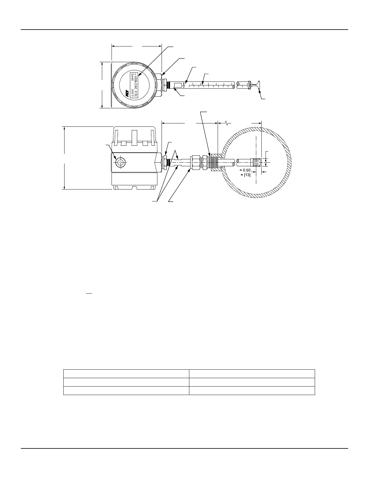
Figure 5 – Flow Element Installation, Compression Fitting ST51A
The flow element is properly mounted when the tip of the flow element is located 0.50 inches (13 mm) past the pipe centerline. The scale
etched on the side of the insertion pipe indicates the length to the tip of the flow element. Follow the steps below to install the ST51A flow
element.
1. Calculate the insertion depth using the equation below.
I = Insertion depth
I.D. = Pipe inside diameter
T = Pipe wall thickness
C = Pipe mounting coupling and compression fitting (installed length)
= 0.50" +
..
+ +
I = __________
2. Mark the insertion pipe at the calculated insertion depth.
3. Apply proper thread sealant to the tapered pipe thread on the compression fitting and secure into pipe mounting coupling.
4. Insert the flow element to the insertion depth mark making sure the orientation flat is aligned parallel to the flow direction. Hand tighten
the compression nut. Compression fitting manufacturer recommends 1-1/4 turns past hand tight.
5. Tighten the compression nut to the torque specified for the corresponding ferrule material as shown in Table 2 below.
Table 2 – Compression Fitting Material
The metal ferrule configuration can only be tightened one time. Once tightened, the insertion length is no longer
adjustable.
XXXX
FLUID COMPONE NTS
INTERN A TIONAL LLC
y
C00584-1-3
MOUNTING ORIEN TATION OF FLATS
TO BE PARALLEL TO FLOW
2X 1/2" NPT,
OPTIONA L M20 x 1.5
ADJUSTABLE COMPRESSION FITTING,
OPTIONA L TEFLON OR METAL FERRULE
ENCLOSURE MEETS EXPLOSION PROOF
WATER AND DUST TIGHT APPRO VALS
OPTIONA L DUAL LINE DIGITAL DISPLAY,
90° INCREMENTAL ROTATION
1/2 OR 3/4 INCH NPT
PROCESS CONNECTION
FLOW ARROW
LASER ETCHED INSERTION SCALE
SERIAL NUMBER
REDUCER
BUSHING
PROTECTIVE SHROUD
OVER PROBE TIPS
0.56
[014]
4.00
[102]
U LENGTH
VARIABLE
4.5
[114]
3.28
[83]
3.56
[90]
L
C