ST51A/ST75A/ST75AV Mass Flow Meters INSTALLATION
Fluid Components International LLC 17
Instrument Wiring
Only qualified personnel are to wire or test this instrument. The operator assumes all responsibility for safe practices
while wiring and troubleshooting.
Install an input power disconnect switch and fuse near the instrument to interrupt power during installation
and maintenance. Always disconnect/shut-off power before wiring.
See Agency Approvals, page 3 and APPENDIX C, page 93 for a complete listing of the instrument’s
safety/hazardous areas approvals.
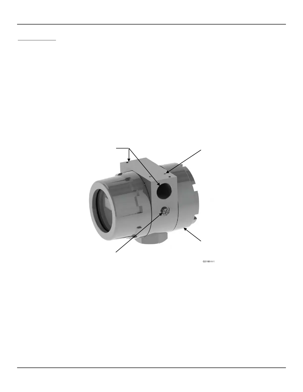
Refer to Figure 15 and Figure 16 below.
A cable/wiring port on each side of the enclosure body is provided for wiring access. These ports are labeled with its thread size (½″ NPT
or M20) via the instrument tag and a label (engraved for stainless steel case) near each port. Either or both ports can be used for wiring.
Use an appropriate plug on the unused port. For the neatest wire routing use the wiring port closest to J7/J8 for all signal wiring and the
wiring port closest to power connector TB1 for power wiring. Provide a service loop for all connections to make rewiring/repairs easier.
An external and internal ground screw (10-32 x ¼″ slotted hex washer) is provided. Use the external ground screw as needed. For
example, use the external ground screw if the probe connection does not make a reliable ground such as a plastic pipe. For EU
applications use only the internal ground screw.
Figure 15 – ST51A/ST75A/ST75AV Wiring Access
WIRING PORT, ½″ NPT or M20
(2 PLACES)
EXTERNAL GROUND SCREW
10-32 x ¼″ SLOTTED HEX WASHER
(Remove to
access wiring)