ST51A/ST75A/ST75AV Mass Flow Meters INSTALLATION
Fluid Components International LLC 7
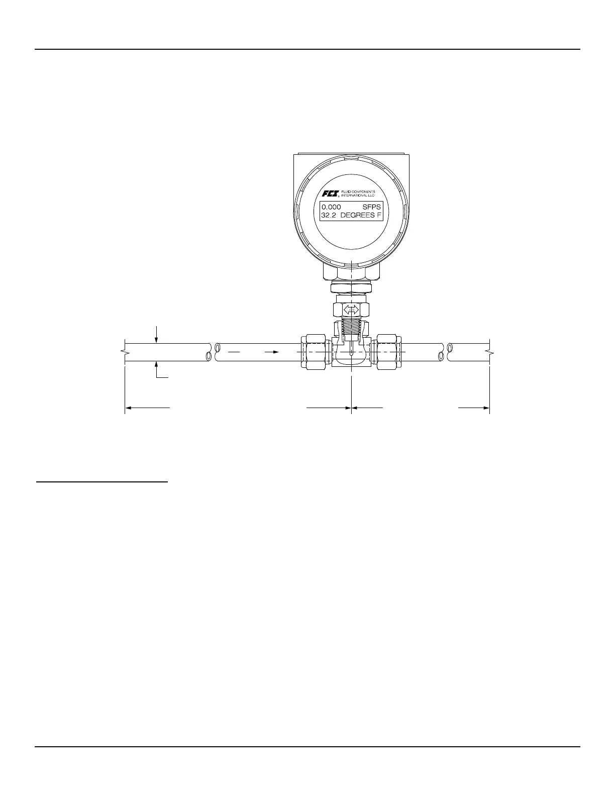
Recommended Straight Run
For optimal flow meter performance FCI recommends a minimum of 20 pipe diameters upstream straight run and 10 pipe diameters of
downstream straight run. See Figure 4 below. Where straight run is limited, FCI offers Vortab flow conditioners for use in applications that
have significant straight run limitations. FCI uses the AVAL application modeling software to predict meter performance in each installation.
AVAL outputs are available to review prior to order placement and will indicate performance expectations both with and without flow
conditioning.
Figure 4 – Recommended Straight Run (ST75A Shown)
Installing ST51A Flow Element
Compression Fitting Mounting
The ST51A is available with both Teflon compression fitting ferrules and metal ferrules. While the Teflon ferrule can be readjusted, it has a
lower process pressure rating and over-tightening may cause it to become stuck or damage the extension pipe. The metal ferrule version
can only be tightened down once and becomes permanently positioned. The ferrule type is indicated in the instrument part number
displayed on the instrument tag. This can be cross-referenced with the Ordering Information Sheet (OIS).
All flow meters have been calibrated with the flow element located at the centerline of the pipe and flow stream as shown in Figure 5.
Couplings and threadolets come in various dimensions. Proper installation requires that the element be measured with consideration to
process connection dimensions and pipe centerline. Install the element in the line with the compression fitting lightly tightened around the
extension, then slowly move the pipe extension forward until the element is at centerline as shown.
Elements are shipped in a protective sleeve. After removing the sleeve, keep the element from sliding through the
compression fitting and contacting the opposing wall with any force. Hitting the pipe wall may damage the element
and upset the calibration (critical in top mount installations).
See APPENDIX A for instrument outline dimensional details.
AFTER LAST FLOW DISTURBANCE
BEFORE NEXT
FLOW DISTURBANCE