INSTALLATION ST51A/ST75A/ST75AV Mass Flow Meters
18 Fluid Components International LLC
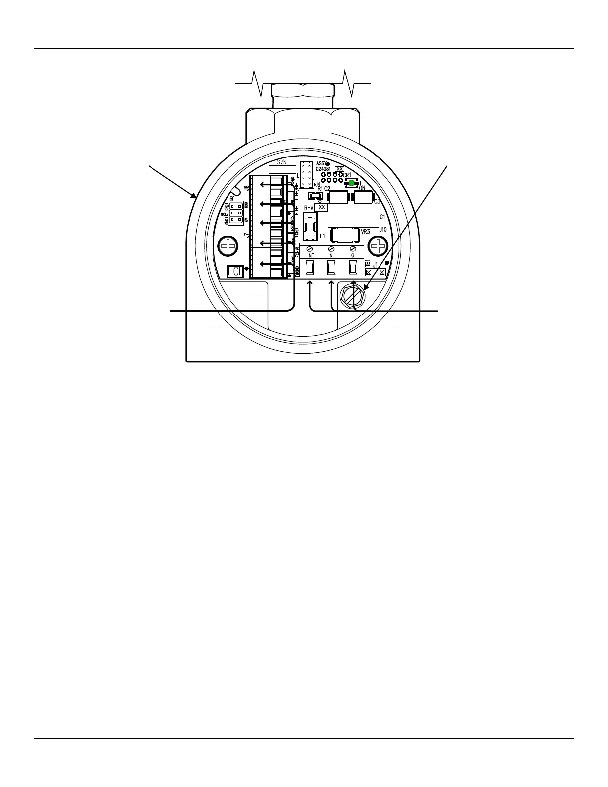
Figure 16 – Recommended Wire Routing/Internal Ground Screw
Accessing the Interface Board Connection Terminals
Turn OFF instrument power source before wiring the instrument.
Use caution inserting wires into electronics housing. The metal ends can damage circuit boards.
Remote Units: Avoid pulling, or inadvertently tugging, the remote cable when wiring the instrument. The sensor
connector/circuit board can be easily damaged by excess pulling of the remote cable.
To access the instrument’s connection terminals first use a .050″ hex key to loosen the set screw locking the enclosure body blind lid (see
Figure 15, page 17). Then unscrew the blind lid from the enclosure. Carefully pull the power and signal wires through the port to avoid
damaging the electronics.
Connect wiring as shown in the diagram in Figure 17, page 19 and the summary list in Table 3, page 21. Reinstall the blind lid when done
making the connections: Tighten the lid one full turn past the point where the O-ring makes contact with the lid, and then tighten the lid set
screw to lock the lid (set screw must not protrude from its threaded hole after tightening).
ESD Precautions
FCI flow meters contain static-sensitive devices. To avoid damage to the instrument observe the ESD precautions
listed below before opening the instrument for wiring.
● Use a wrist band or heel strap with a 1 MΩ resistor connected to ground.
● Use a static conductive mat on the work table or floor with a 1 MΩ resistor connected to the ground when working on the instrument in
a shop setting.
● Connect the instrument to ground.
● Apply antistatic agents such as Static Free made by Chemtronics to hand tools used on the instrument.
● Keep high static-producing items away from the instrument.
SCREW, 10-32 x ¼″
(BLIND LID REMOVED,