INSTALLATION ST51A/ST75A/ST75AV Mass Flow Meters
20 Fluid Components International LLC
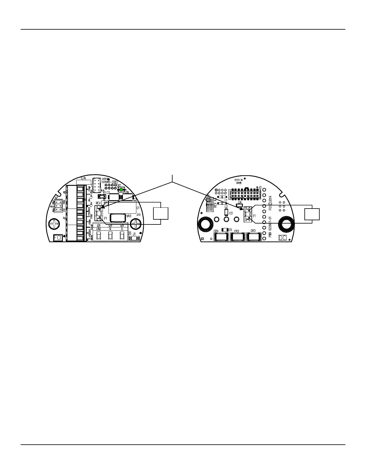
POWER FUSE REPLACEMENT
Input power overload protection is provided by a 1.5 A slo-blo surface mount fuse installed in a fuse holder on the interface board. (To
access this board see Accessing the Interface Board Connection Terminals, page 18.) Refer to Figure 18 below.
● AC-powered instruments: Locate the fuse at the center of the interface board on top.
● DC-powered instruments: Locate the fuse at the center of the interface board on the back (solder side). With power OFF remove two
securing 6-32 x ½″ Phillips pan head screws and star washers from the DC-powered interface board. Pull board straight up from mating
sockets to access the fuse at the back.
To check for a blown fuse:
1. Turn instrument power OFF.
2. Access the interface board (see text above).
3. Using an ohmmeter touch metal cap at each end of fuse with the test leads. Any reading other than a short (i.e., open circuit)
indicates a blown fuse. Replace with Littelfuse 454 Series fuse, part no. 045401.5.
Figure 18 – Input Power Fuse Locations
TEST
LITTELFUSE 454 SERIES
INTERFACE BOARD
INTERFACE BOARD
SOLDER SIDE
(Remove Interface Board to
access fuse. See manual text.