INSTALLATION ST51A/ST75A/ST75AV Mass Flow Meters
24 Fluid Components International LLC
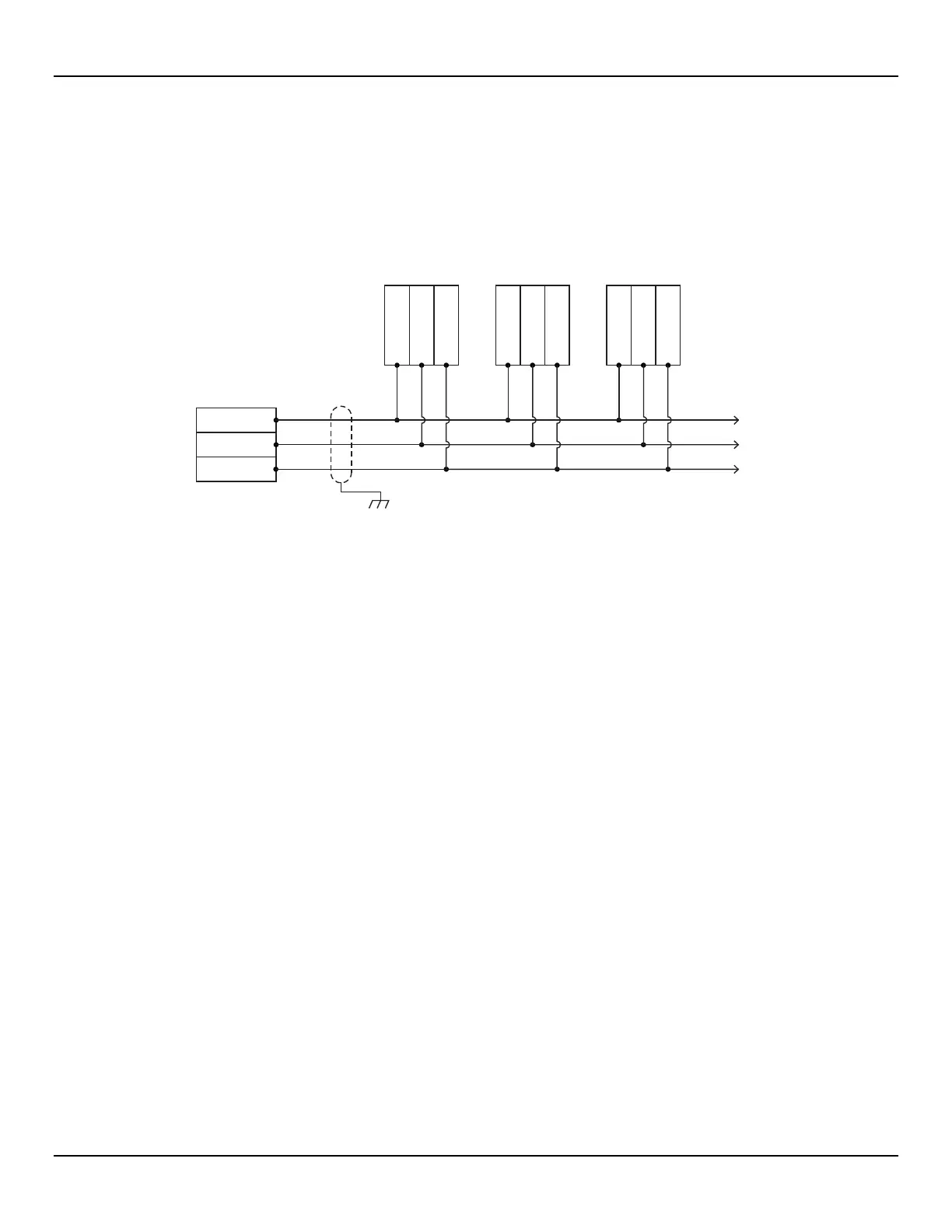
Modbus Connections
The ST51A/ST75A/ST75AV Modbus interface is provided by interface board connector pins J7-1 [Data (A-)], J7-2 [Data (B+)], and J7-5
(Gnd/Common). Refer to Figure 17, page 19. Connect the instrument to a Modbus device/network using a 2-wire RS-485 connection
scheme as shown in Figure 22 below. For details on Modbus operation refer to Modbus Operation, page 56.
If using a shielded Modbus cable, connect cable shield to chassis/earth ground at one end only.
Figure 22 – Modbus Wiring
RS-485 MASTER
2-WIRE ONLY DEVICE
DEVICE 1 DEVICE 2 DEVICE 3
One twisted wire pair
plus Gnd/Common.
Cable Shield
(To Chassis/Earth
Gnd)
To remaining
RS-485 Devices
DATA (B)+
DATA (A)-
GND
DATA (B)+
DATA (A)-
GND
DATA (B)+
DATA (A)-
GND
DATA (B)+
DATA (A)-
GND
C01415-1-1