ST51A/ST75A/ST75AV Mass Flow Meters INSTALLATION
Fluid Components International LLC 25
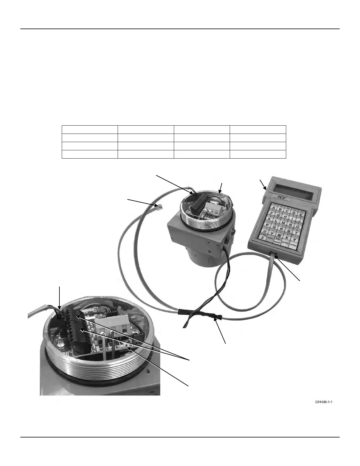
Serial Interface Connector J9
An RS-232 serial port is provided via a .100″ 2 x 3 header connector (J9) on the interface board (remove blind lid for access, see Accessing the
Interface Board Connection Terminals, page 18). The J9 pinout is listed in Table 4 below. Plug the serial cable adapter assembly (025859-01),
included in the FCI Flow Meter Communications kit (part no. 014108-03), onto the J9 header as shown in Figure 23 below. Then plug the other
end of the cable (the longer of the two modular connector cable ends) into an FC88 handheld calibrator or a serial port adapter (DB9 and DB25
serial adapters included in the optional communications kit) as required. The block diagram in Figure 24 shows the connections available using the
serial cable adapter. Refer to Instrument Configuration and Setup Using the Service Port (RS-232) on page 27 for details on using the serial port.
The instrument’s serial port is intended for temporary use only.
Table 4 – Serial Port J9 Pinout
1
1
Note: 1. FGND = Filtered Ground
Figure 23 – Serial Cable Adapter 025859-01 Plugged Into Flow Meter J9 Header
(SHORT CABLE, FOR
ST51A/ST75A/ST75AV ONLY)
(SHORT CABLE, FOR
ST50/ST51/ST75/ST75V ONLY)
FLOW METER BODY
(BLIND LID REMOVED)
PLUG PLUGGED
INTO FC88
(Can also plug into
Serial/USB adapter)
SERIAL CABLE ADAPTER
025859-01
SIGNAL TERMINAL
BLOCKS, J7 & J8
PLUGGED INTO J9 HEADER
(IMPORTANT: Orient Latch
As Shown)