ST51A/ST75A/ST75AV Mass Flow Meters OPERATION
Fluid Components International LLC 29
Table 6 – Typical Serial Interface Top Level Commands for Flow Meter Configuration
Normal operating mode: All outputs are active.
Set English/Metric flow units; set up pipe dimensions for volumetric units.
Set 4-20 mA and pulse output configuration.
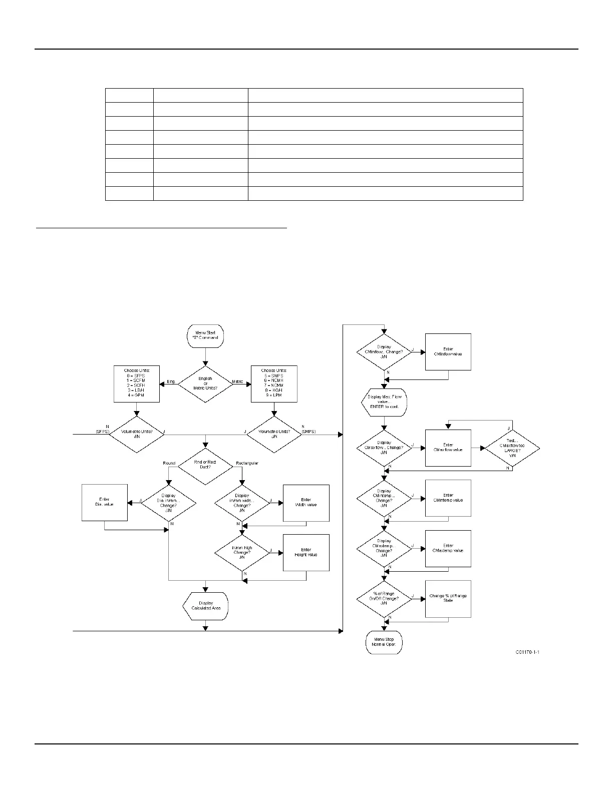
Z Menu: Configure Flow Units and 4-20 mA Output Scaling
Use the Z menu to change flow units. Note, however, that changing units requires rescaling of the unit (set new zero and span). The 4-20 mA Zero
and Span can be changed from the original calibration, provided the new values are within the original calibrated range; i.e., if the original
calibration was 1 to 100 SCFM (4-20 mA), the new zero (4 mA) must be equal to or greater than 1 SCFM and the new span (20 mA) must be
equal to or less than 100 SCFM. The flowchart in Figure 25 below gives an overview of the instrument’s Z menu programming.
The Z menu is passcode protected when the totalizer function is enabled. Contact the factory for details.
Figure 25 – Z Menu Command Structure: Units and Scaling Setup