INSTALLATION ST51A/ST75A/ST75AV Mass Flow Meters
12 Fluid Components International LLC
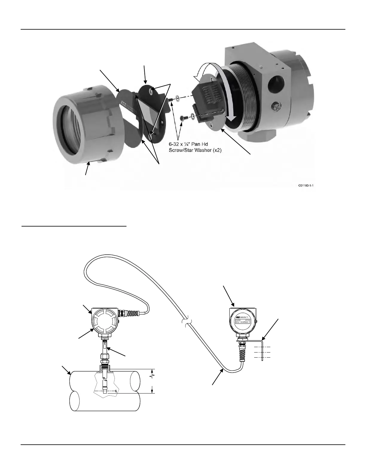
Figure 8 – Display Re-positioning
Installing the Remote Flow Meter System
Remote transmitter instruments include the following components: local enclosure containing the flow element sensor, remote enclosure
containing the display/electronics and interconnecting remote cable. Both enclosures are explosion-proof ATEX/IECEx rated. A typical
remote flow meter system is shown in Figure 9 below.
Figure 9 – Typical Remote Flow Meter System (ST51A with ½" NPT Cable Port Shown)
C01314-1-1
U LENGTH
DIMENSION
TRANSMITTER/
DISPLAY BOARD
(TURN THIS BOARD 90°
INCREMENTS TO POSITION DISPLAY)
BEZEL GUIDE POST (2 PLACES)
ENCLOSURE
ENCLOSURE,
REMOTE CABLE
(NPT CONFIGURATION SHOWN)
ASSEMBLY