OPERATION ST51A/ST75A/ST75AV Mass Flow Meters
52 Fluid Components International LLC
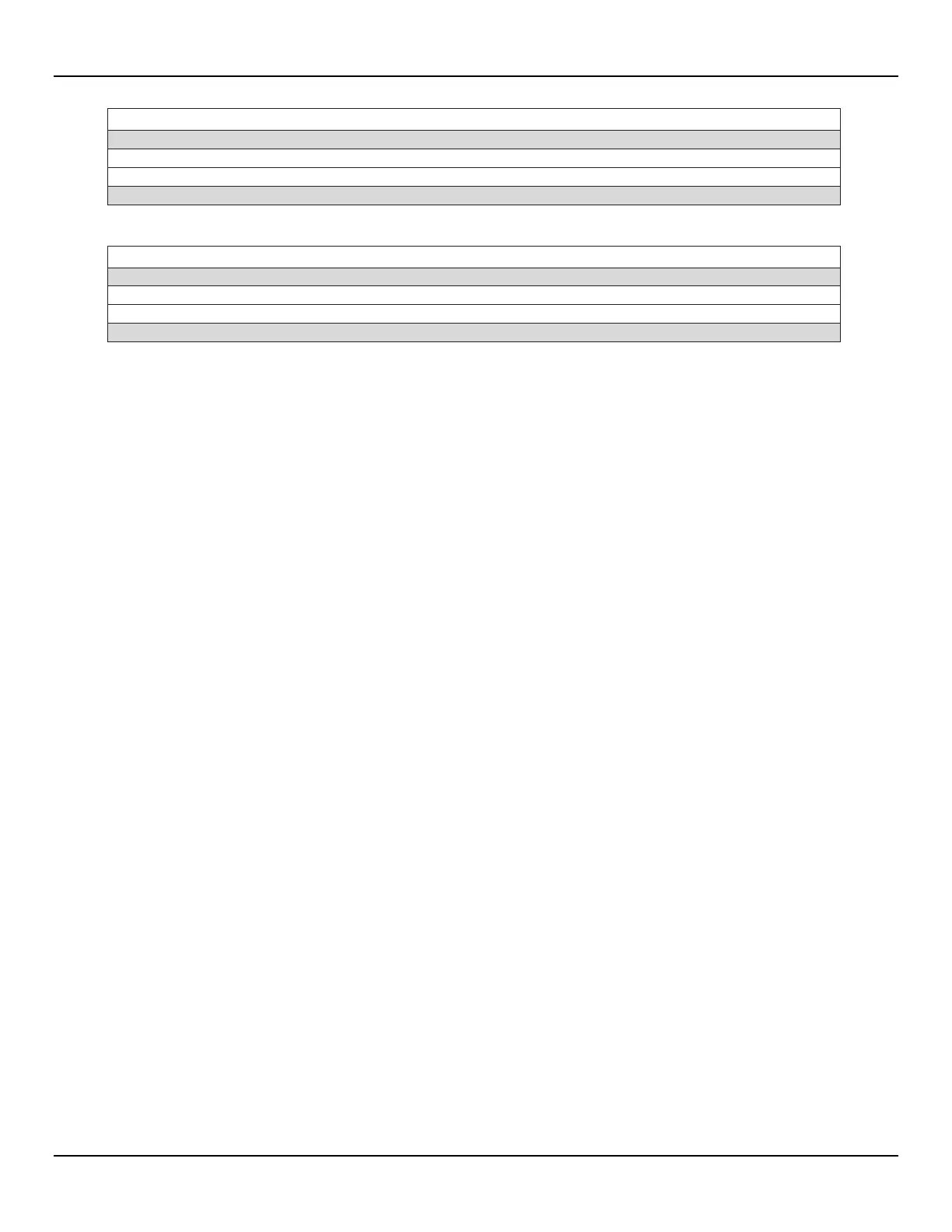
Command 163: Trim DAC Zero – Measured Current Chan #2 (in mA)
Ext. Measured Current Ch. #2 Level (mA units)
Actual Measured Current Ch. #2 Level (mA units)
See Table 16, page 53, for response code list.
Note: 1. The value returned in the response data bytes reflects the rounded or truncated value actually used by the device.
Command 164: Trim DAC Gain – Measured Current Chan #2 (in mA)
Ext. Measured Current Ch. #2 Level (mA units)
Actual Measured Current Ch. #2 Level (mA units)
See Table 16, page 53, for response code list.
Note: 1. The value returned in the response data bytes reflects the rounded or truncated value actually used by the device.
HART Command Bit Assignments
Command Status Bytes
The HART command response data field includes a status message in the first two bytes. The first byte (0) is the Comm Error/Response code.
The second byte (1) is the Device status. Byte 0 indicates either a communication error or a command-specific response code if no
communication error exists. Note that within the first byte, bit b7 is either set or cleared to indicate that the byte indicates a comm error or a
command-specific response code, respectively. Table 15 summarizes the command status bytes. Table 16 summarizes the command-specific
response codes.