ST51A/ST75A/ST75AV Mass Flow Meters INSTALLATION
Fluid Components International LLC 21
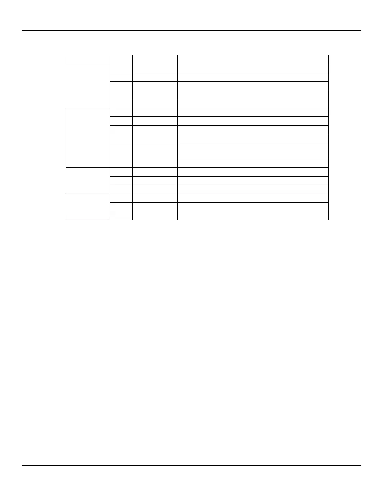
Table 3 – Power and Signal Wiring Summary
J8, Signal
Internal HART connection / 4-20 mA Ch. #1 (+)
External HART connection (-)
3
Internal HART connection / 4-20 mA Ch. #1 (-)
External HART connection (+)
4-20 mA Ch. #2 – default parameter assignment: Temperature
J7, Signal
Return for 4-20 mA Ch. #2 and Source/Sink, and Gnd/Common
for Modbus.
TB1, AC Power:
85-265 VAC
(CE Mark: 100-240 VAC)
AC Line (typical wire color: black or brown)
AC Neutral (typical wire color: white or blue)
Earth Ground (typical wire color: bare, green or green/yellow)
TB1, DC Power:
18-36 VDC
DC Positive (typical wire color: red or white)
DC Negative (typical wire color: black)
Earth Ground (typical wire color: bare, green or green-yellow)
To maintain isolation between power input and output signals, keep GND and EARTH GND (chassis ground) separate.
Signal Connections
The J7 and J8 terminal blocks are provided for signal connections. These terminal blocks have 3.5 mm pitch spacing and accept 28 AWG
(min.) to 14 AWG (max.) wires. Observe signal wire routing as described in Instrument Wiring, page 17.
4-20 mA Analog Outputs
The instrument is provided with a 4-20 mA current loop as an integral part of the HART signal output and a second 4-20 mA current loop
for general purpose use. Refer to Figure 17, page 19 and Table 3, page 21 for the HART loop and general purpose 4-20 mA loop
connector pin assignments. By default Channel 1 (HART) is assigned flow and Channel 2 (general purpose) is assigned temperature. See
also V Menu: Configure Outputs (4-20 mA and Source/Sink Outputs), page 30 for details on setting up the analog outputs.