ST51A/ST75A/ST75AV Mass Flow Meters INSTALLATION
Fluid Components International LLC 19
The above precautions are minimum requirements. The complete use of ESD precautions can be found in the U.S. Department of Defense
Handbook 263.
Interface Board Connections
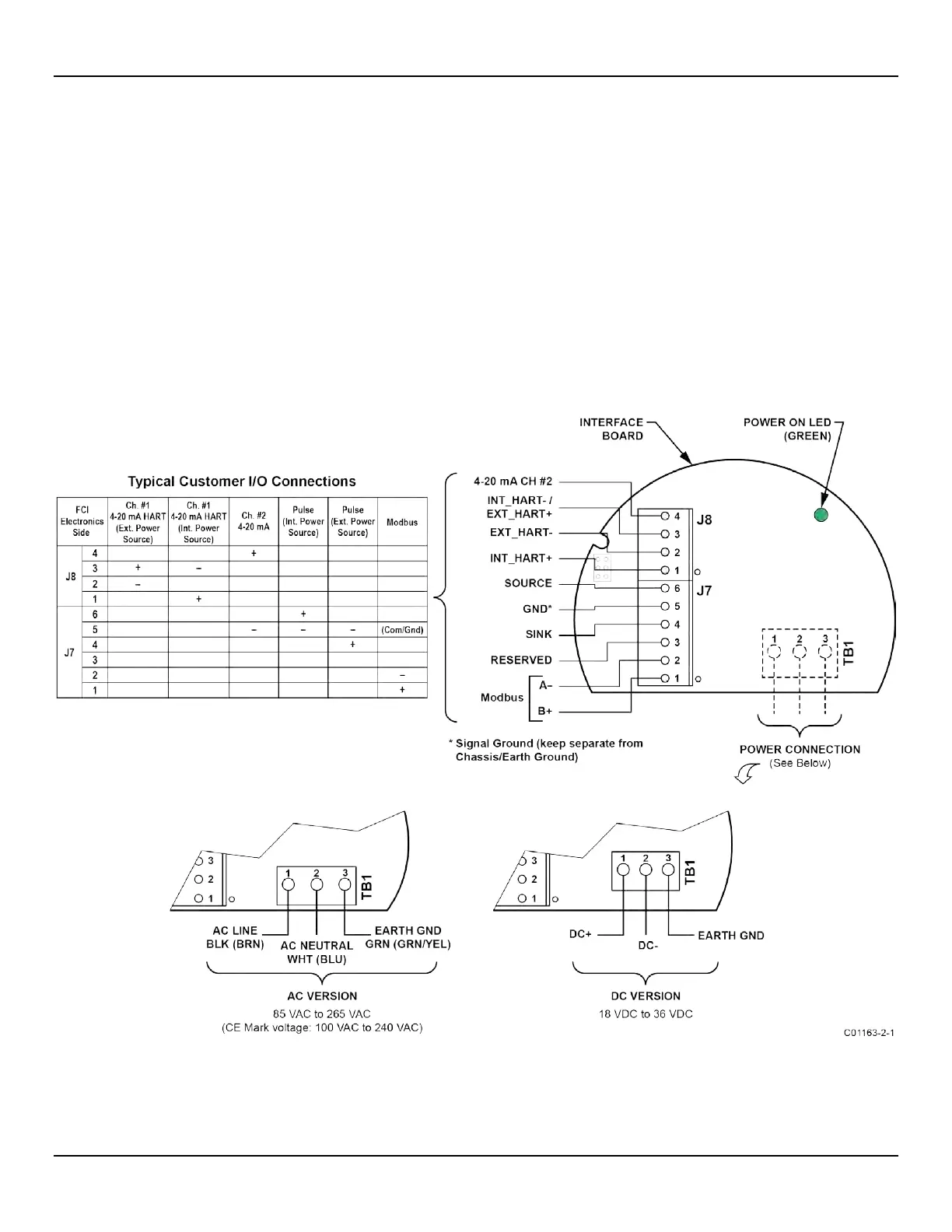
Power and signal connections are made at the interface board. Refer to Figure 17 below.
Power Connections
Turn OFF instrument power source before wiring instrument power.
The instrument is offered in DC and AC input power configurations. DC units include DC interface and power supply boards. Similarly, AC
units include AC interface and power supply boards. Interface boards are specifically marked for AC or DC power. Only connect the power
specified on the wiring module as shown in Figure 17. Both AC and DC inputs require a ground wire to be connected. Input power terminal
blocks accept 14-26 AWG wire. Observe power wire routing as described in Instrument Wiring, page 17.
O
NBOARD POWER ON LED INDICATOR
An LED on the interface board lights up green when instrument power is ON. The LED is visible only when the blind lid is removed, which
serves to alert the user that power is active when accessing the instrument’s signal/power wiring.
Figure 17 – Power and Signal Wiring Terminals