ST51A/ST75A/ST75AV Mass Flow Meters INSTALLATION
Fluid Components International LLC 23
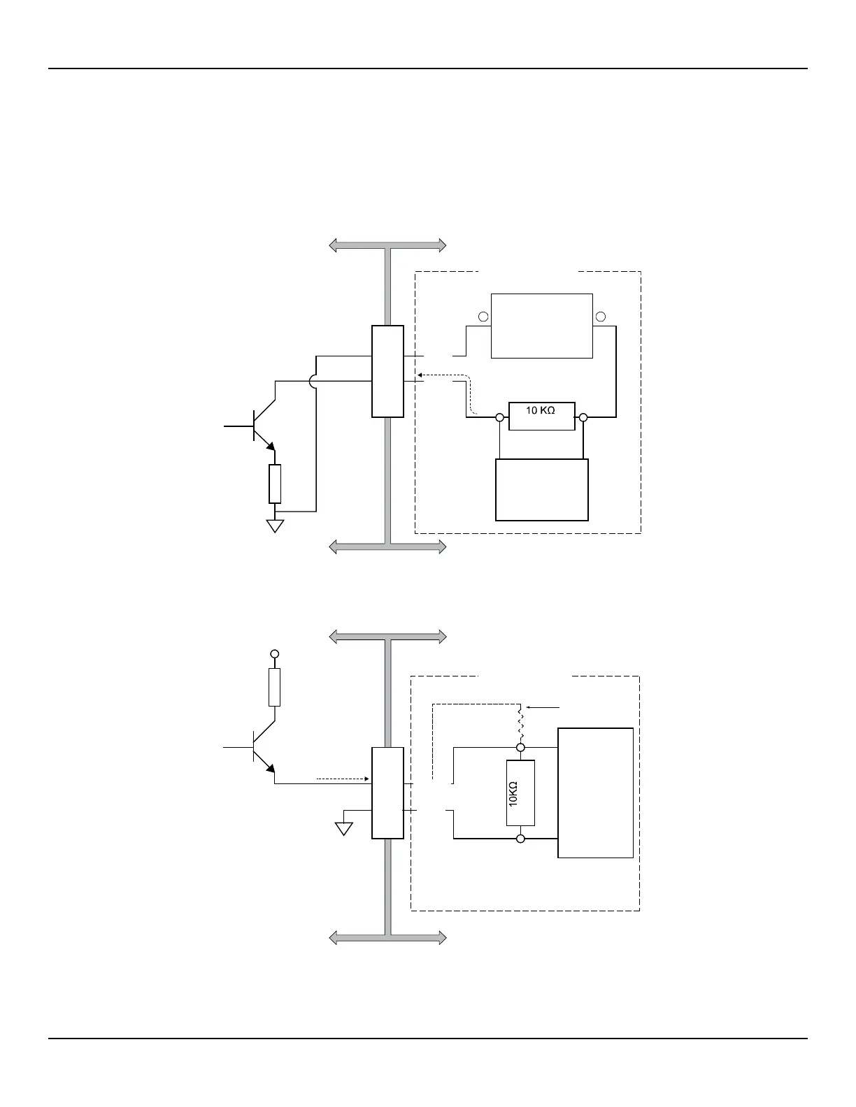
Pulse Output and Alarm (Source/Sink)
Wire the source/sink outputs via the J7 terminals as required for your device (using sink or source output as appropriate) as shown in Figure 20
and Figure 21 below. Either output can be used as a pulse output or a level (alarm) output. Observe the output power limits listed below.
● Sink Output: 40 VDC maximum, 150 mA maximum (external, user-supplied power source)
● Source Output: 22 ±2 VDC output, 25 mA maximum (supplied by the flow meter)
See Source/Sink Output Configuration, page 32 for details on configuring the output as a pulse or level output.
Figure 20 – Sink Output
Figure 21 – Source Output
(Typical)
External 24-40 VDC
Power Supply
150 mA max.
External Device
(Counter, etc.)
COM
SINK
USER WIRING
J7
FLOW METER SIDE USER SIDE
5
4
C01165-1-2
CURRENT FLOW
–
+
J7
(Typical)
External
Device
(Counter, etc.)
24 VDC
25 mA max.
GND
USER WIRING
FLOW METER SIDE USER SIDE
SOURCE
Alternate wiring
see note below
Note: Use voltage divider resistor
network if flow meter source voltage
(24 VDC) exceeds your device input.
6
5
C01166-1-1
CURRENT FLOW