1672/1673 FC/1674 FC
Users Manual
26
5. Connect the mains line cord (or the test leads) to the Tester and the zero adapter. You can
zero two or three test leads in the R
LO
function.
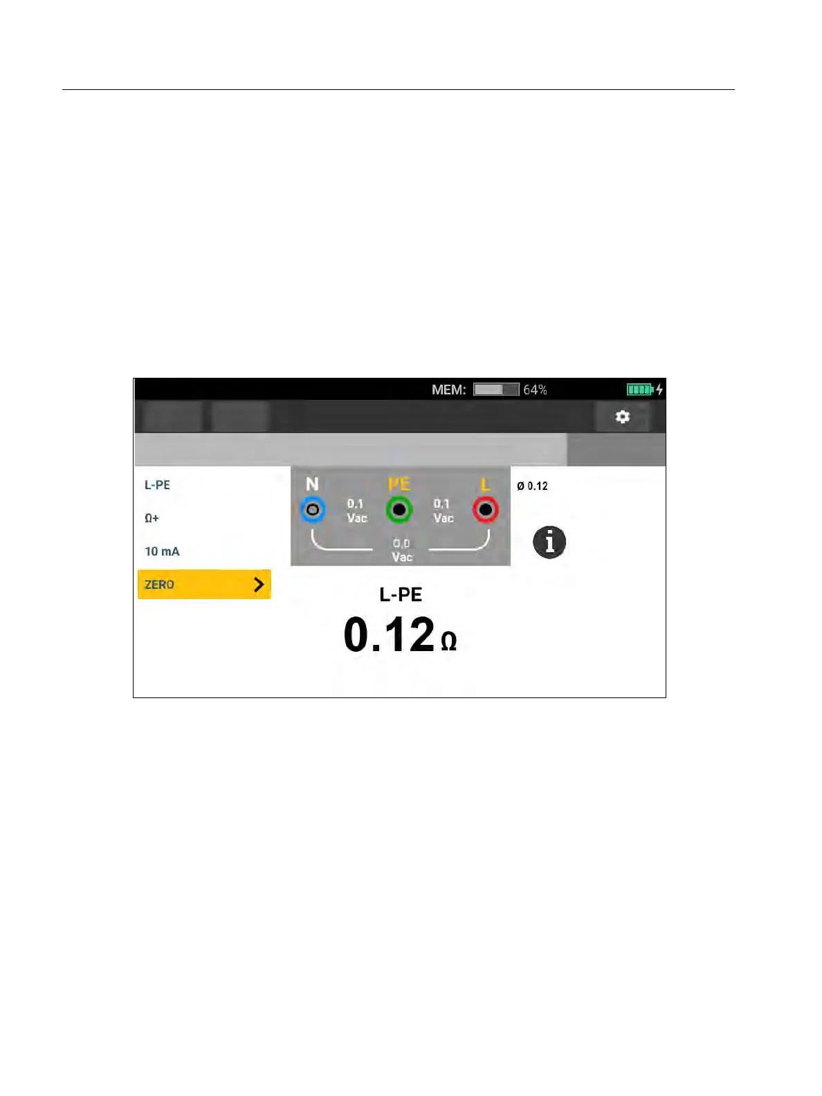
6. Tap ZERO (or navigate to ZERO with the rotary dial and push the center of the dial) to start
the zero operation.
and the offset value show on the display. The beeper sounds with each completed zero
value. See Figure 6
The Tester measures the lead resistance, stores the value, and subtracts it from
measurements. The resistance value is retained when the power is turned off. If the Tester
is set to the same function with the same test leads or mains cord, you do not need to
repeat the zero operation.
Figure 6. Zero Display
7. If the display reads >3.0 Ω:
For a Loop (Z
I
) test, check that all 3 leads are connected.
For a Continuity (R
LO
) test, check that all 3 leads are connected.
To zero 2 leads in the R
LO
function, use L-PE, L-N, N-PE to select the shorted leads and
confirm
annunciator shows.
Check for damaged leads.
If the tester battery voltage is too low, the Tester will not zero.
If the Tester shows invalid values, reset the zero values:
1. Hold the leads apart.
When the display reads >3.0 Ω the
annunciator disappears and clears the stored
compensation value for that test.
Functions
Form
Continuity
No Limit
No project selected