4.10-4 Section 4: Using the Model 9100: Mark/Period Function
Final Width = 215mm
Help Available!
Section 3 Editing Tutorials.
4.10.4.1
'Mark' and 'Period' Time-Intervals, High and Low Voltage Levels
Mark and Period time-intervals, High Level and Low Level voltage values can be
changed using 'Digit' and 'Direct' edit facilities as described in Section 3. On the 'Mark/
Period'
menu screen (illustrated on page 4.10-2) the high level value is placed beneath the
period time interval value on the left, and the low level on the right.
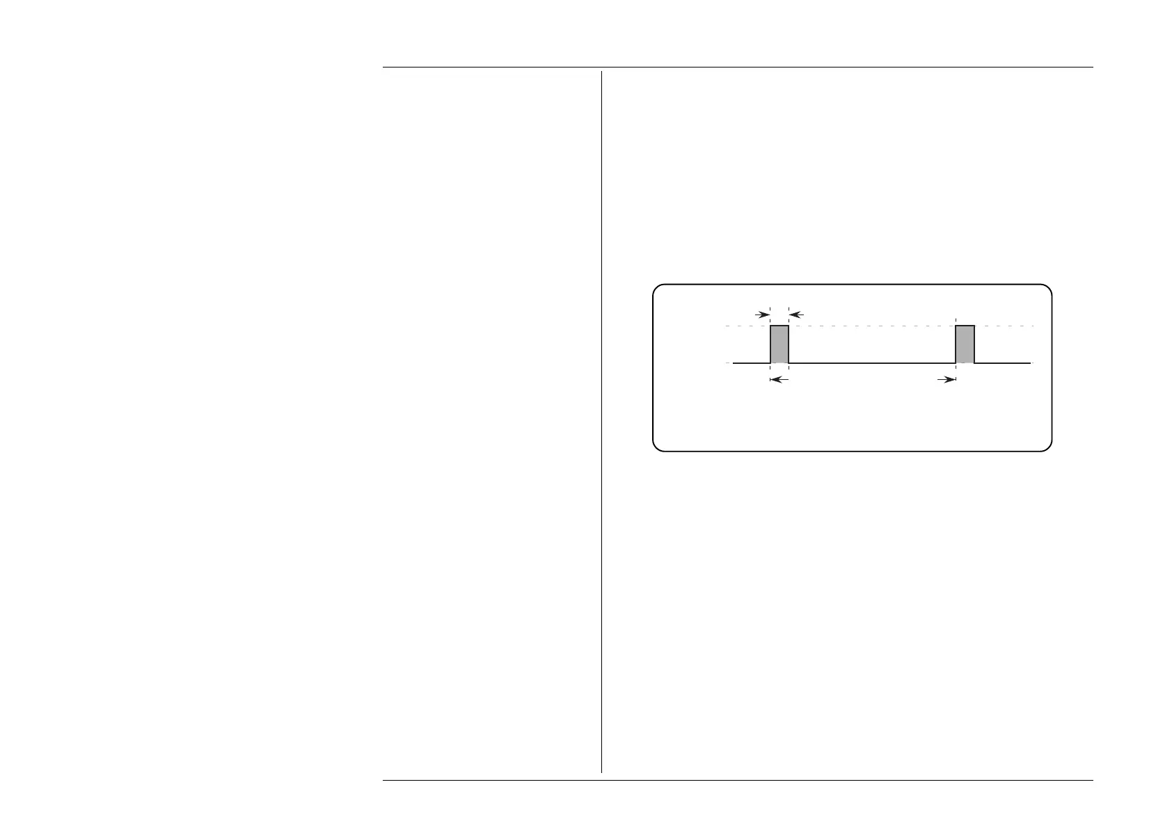
Default Output Waveshape
The default output is a 100Hz rectangular wave (1:10 mark/period ratio; 1:9 mark/space
ratio; i.e. 10% duty cycle) with its low level at 0 volts, and its high level at +5V, as shown
below in Fig 4.10.1:
4.10.4 Value Editing
Pulse Width = 1ms
Space = 9ms
Repetition Interval = 10ms
Repetition Rate = 100Hz
High Level
= +5V
Low Level
= 0V
Fig. 4.10.1 Mark/Period Function —
Default Output Waveshape
High and Low Signal Level Switching
The effect of changing the values, appearing in the High and Low Level positions on the
screen, is to alter the voltages between which the rectangular output waveform switches.
High and Low Signal Level Limits
The high and low signal levels are respectively the most-positive and most-negative
excursions of the output signal, and cannot be set outside the following magnitude limits:
Up to ±6.0V Output:
0.6µs ≤ Period; 0.30µs ≤ High Interval; 0.30µs ≤ Low Interval.
Up to
±30V Output:
1ms ≤ Period; 10µs ≤ High Interval; 10µs ≤ Low Interval.
In addition, the High Level cannot be set equal to or more negative than the Low Level.