Section 4: Using the Model 9100: Thermocouple Function 4.14-5
Final Width = 215mm
4.14.4 Delivery of DC Voltage Thermocouple Simulation
4.14.4.1 Simulation Drive
The simulation is available only through the 'D-Type' socket
beneath the main terminals. Correct interconnections,
terminations and materials must be used to maintain traceability.
It is assumed that the UUT will use a reference-junction method
of compensation in the measurement circuit.
4.14.4.2 Software Compensation (Fig 4.14.1)
One of the 9100 accessories is an isothermal block, which
connects directly into the D-type socket on the front of the 9100.
This block supports two reference junctions which terminate
directly as a two-pin socket, into which a standard thermocouple
extension lead for the appropriate thermocouple type can be
inserted.
The reference junctions are formed by the contacts between the
copper socket pins and the plug pins of the external extension
lead.
A thermistor, mounted in thermal conduction with the block and
connected to the 9100 through the D-type connection, senses the
temperature of the two junctions. This measurement is converted
to provide an equivalent reference junction voltage, which in
turn is used to compensate for the effect of the junctions'
thermoelectric EMFs.
When the Model 9105 leadset is in use, the same connections for
the isothermal block are available at a D-type socket, fitted on
the end of the leadset connector unit, under the workmat (refer
to sub-section 4.2).
The automatic process of updating the compensation, after
sensing block temperature, is carried out on the following
occasions:
a. At the point of selecting the Thermocouple function;
b. At intervals of several seconds, when the Thermocouple
function is selected and Output is On.
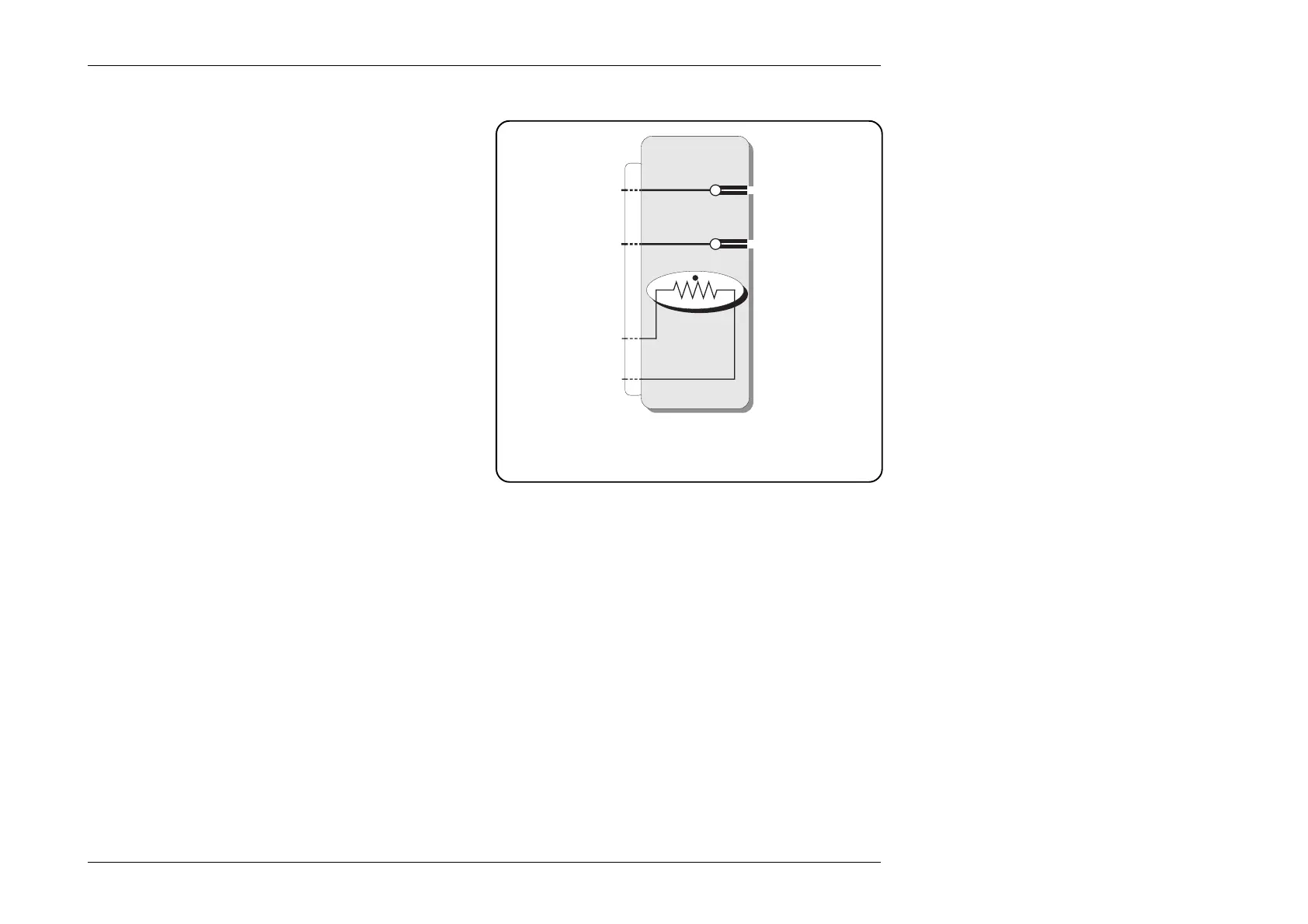
Fig. 4.14.1 Reference Junctions on Isothermal
Block, with Thermistor Temperature Sensor for
Software Compensation
Iso-Thermal Block
Thermo-
couple
Type
Socket
Thermistor
Reference-
Temperature
Sensor
Reference
Junctions
D-Type
Plug
4.14.4.3 Simulation Analog
Most thermocouples are inherently non-linear, and thermocouple
thermometers incorporate circuitry or software to permit linear
temperature scales to be used. The 9100 therefore simulates the
non-linearity for each type in order to test the UUT.
The temperature set on the 9100 front panel screen is ultimately
converted to a compensated output voltage. For each
thermocouple type, a look-up table in firmware converts the
temperature setting into a voltage demand, based on the type's
published characteristics. The setting resolution of 0.1°C is
obtained by interpolation between points on the look-up table.
4.14.4.4 External Connections
After compensation for the reference junctions, the voltage
appears on the pins of the extension lead (the correct lead must
be used, which will have wires made of the correct extension
alloys, so that no further EMF-producing junctions are produced).