4.18-6 Section 4: Using the Model 9100: Insulation/Continuity Function (Option 135)
4.18.4 Icons and Other Screen Information
When Insulation mode is active (i.e. the insulation icon appears at the top left of the
screen), there is a bargraph icon representing which of the two available current modes
is selected for the particular requested resistance. The output defaults to SuperI (Super
Current) mode, i.e. the bargraph is shown all the way up. This is the most suitable current
for the class of insulation testers for which the Option 135 is designed. However, some
testers that operate at a lower test voltage/current may not be ideally suited to the internal
dynamic range of the Option 135, and the two current modes provided by this option
allow the user to compensate for this. Refer to section 4.18.7.2 for a more detailed
description.
The 16
th
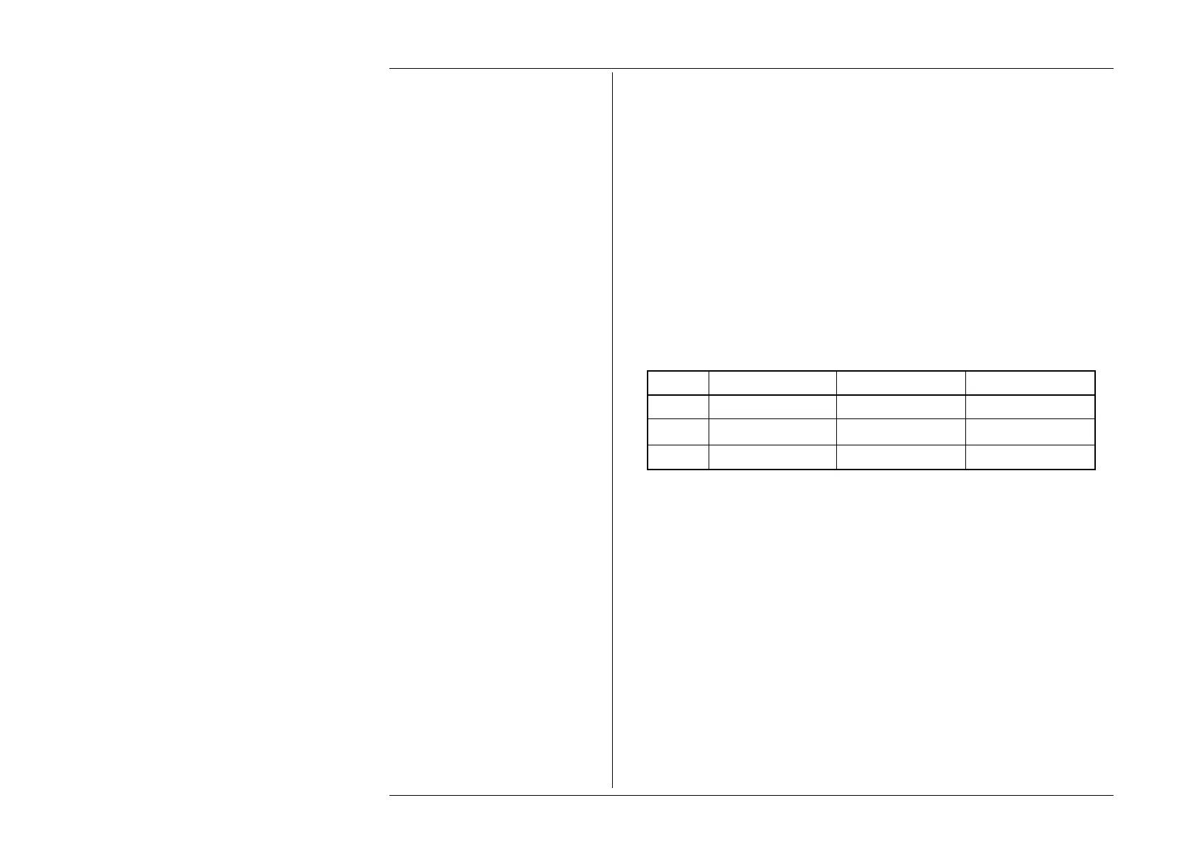
edition of the I.E.E. wiring regulations (713-02 to 713-12) requires that an
insulation tester must be capable of providing the following test currents and voltages into
the specified load impedance:
Range Load impedance Minimum Current Minimum Voltage
250V 250kΩ 1mA 250.0V
500V 500kΩ 1mA 500.0V
1000V 1MΩ 1mA 1000V
In order to ascertain that the UUT is providing sufficient test voltage at each of its
respective test points, the output voltage across the load must be measured when
calibrating the unit. Model 9100 Option 135 provides a display of UUT output voltage
and current in the top right-hand corner of the screen to enable the user to confirm that
this is the case. When a (high) voltage is not being applied, these values default to X.XXX
xA and X.XXX xV respectively.