Section 4: Using the Model 9100: Insulation/Continuity Function (Option 135) 4.18-7
The Continuity function operates over the following three hardware ranges:
Absolute Resolution Span of Values Nominal Span Value
0.1mΩ 00.0000Ω 40.0000Ω 40Ω
1mΩ 000.000Ω 400.000Ω 400Ω
10mΩ 0.00000kΩ 4.00000kΩ 4kΩ
The operation of the Continuity function is essentially the same as the existing Active
Resistance function, with the following exceptions:
1. The output resistance is permanently locked into ‘4-WIRE’ mode. This is because at
the low resistance values and high test currents which continuity testers use (at least
200mA into a short circuit), the series resistance of the test leads and the internal
resistances of the UUT and 9100 would cause measurement inaccuracies. Always
ensure that you connect the UUT to the instrument in 4-wire mode when conducting
continuity tests (connect the HI to Sense HI and the LO to Sense LO terminals at the
input terminals of the UUT, using either stackable insulated plug leads or the red and
black terminals of the 9105 lead mat).
4.18.5 Continuity Mode Operation
Access to the Continuity mode is made via the Continuity screen softkey:
Ω
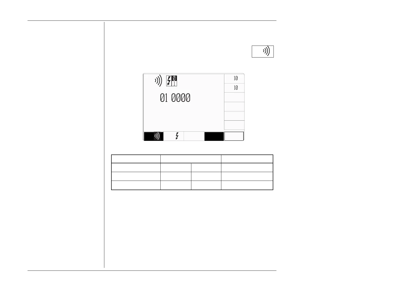
When Continuity mode is selected, the following default screen appears:
date time
x
÷
Ω
I = X.XXX xA
Ω
Ω∆
.
Ω
4 WIRE