3-10 Section 3: Model 9100 Controls: Modes of Operation
Final Width = 215mm
TODAYS DATE TIME
TODAYS DATE TIME
Remote Operation via the
IEEE-488 interface —
Addressing the 9100
1. When the 9100 is set for remote
operation, control is removed from
the front panel and given to an
external controller, which is
programmed to carry out the
procedure for the required
application.
2. Communication is set up between
the 9100 and its controller via the
IEEE-488 bus, connected into an
interface within the 9100 through
J101 on the rear panel (refer to
Section 2, Sub-section 2.8.1).
3. Commands from the controller are
addressed specifically to the 9100
using an address code, which can
be a number in the range 0-30. For
the 9100 to respond, this number
must be matched by the same
number programmed into the 9100
using the procedure given in the
column on the right.
4. Remote operation of the 9100 via
the IEEE-488 interface, using the
IEEE-488.2 and SCPI protocols, is
fully described in Section 6 of this
Handbook (Volume 2).
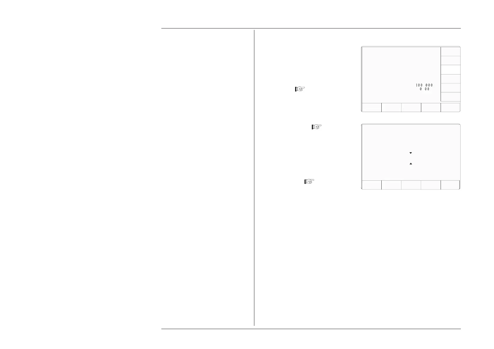
3.3.2.5 'BUS ADDRESS'
1. The 9100 IEEE-488 bus address
can be set to any number within
the range 0 to 30. For access from
the 'Present Settings' screen, press
the BUS ADDRESS screen key
on the right
2 The 9100 transfers to the 'Change
the address' screen
3. Use Digit edit or Direct edit to set
the required bus address number.
If using Direct edit, type the
number on the keypad, then press
the ↵ key.
4. Press EXIT to return to the 'Present
Settings' screen
The new number will be registered in
the interface, and the 9100 will respond
to IEEE-499.2 commands bearing that
address code.
Configuration
Change the address by using
digit or direct editing.
Configuration
Present Settings:
Language English
Power-up mode Manual
Bus Address 1
Printer NONE
Results Card Disabled
Safety Voltage
.
V
Border Line
7
.
%
Scope option Option 600
Crystal option High acc
Ser. No. XXXXXX Rev. XXX
SELECT
LANG
POWER
UP MODE
BUS
ADDRESS
RESULTS
CARD
PRINTER
VOLTAGE
LIMIT
DATE
TIME
BORDER
LINE
MORE
Bus address =
22
EXIT
CLEAR
USER
LIST