Model FT2 101364
2. Installation
2.1. Scope
This section describes how to install the FT2 flowmeter and how to get started.
The following, general precautions should be observed:
a. Exercise care during handling to avoid damaging the probe, sensor or enclosure.
b. The enclosure cover must be closed except during installation and programming.
c. Mounting FT2 in direct sunlight can cause the temperature inside the enclosure to increase
beyond design limits, resulting in failure of the LCD display and reduced component life. It
is recommended that a sunshade be installed to avoid direct sunlight.
d. Ensure that the arrow on the flow body is pointing in the direction of flow.
e. Do not install the FT2 enclosure near an igniter, igniter controller or switching equipment.
f. Do not install an external power supply in a cabinet containing an igniter controller or
switching equipment.
g. Do not power the power supply with an AC power source that is also used to power an igniter
or igniter controller.
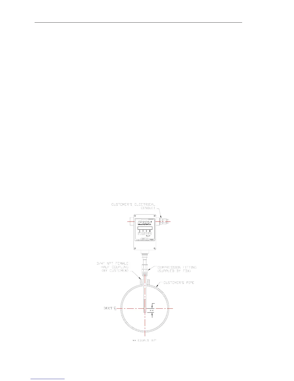
2.2. Insertion Style
2.2.1. Mounting – Insertion Style
The Model FT2 is mounted through a ¾-inch hole and a ¾-inch female NPT half coupling
provided in the customer’s pipe. Installation procedures must be a combination of end user’s best
engineering practices, in compliance with local codes, and manufacturer’s recommendations.
Insertion style flowmeters are not recommended for pipes smaller than 1½”.
Figure 2-1 Insertion Style
Page 10 Fox Thermal Instruments, Inc., 399 Reservation Road, Marina, CA 93933