101364 Model FT2
be used. Connect the wires to connector TS1 being careful to connect with the correct polarity (bring
DC wires in through the right-hand conduit hub).
Signal Wires
Always use a separate shielded cable for each output signal, select the proper wire gauge. The
recommended wire gauge is 18 to 22 AWG. The cable shield
should not be connected at the
flowmeter, the shield should be connected at the AC ground terminal at the power supply or
instrumentation AC ground terminal.
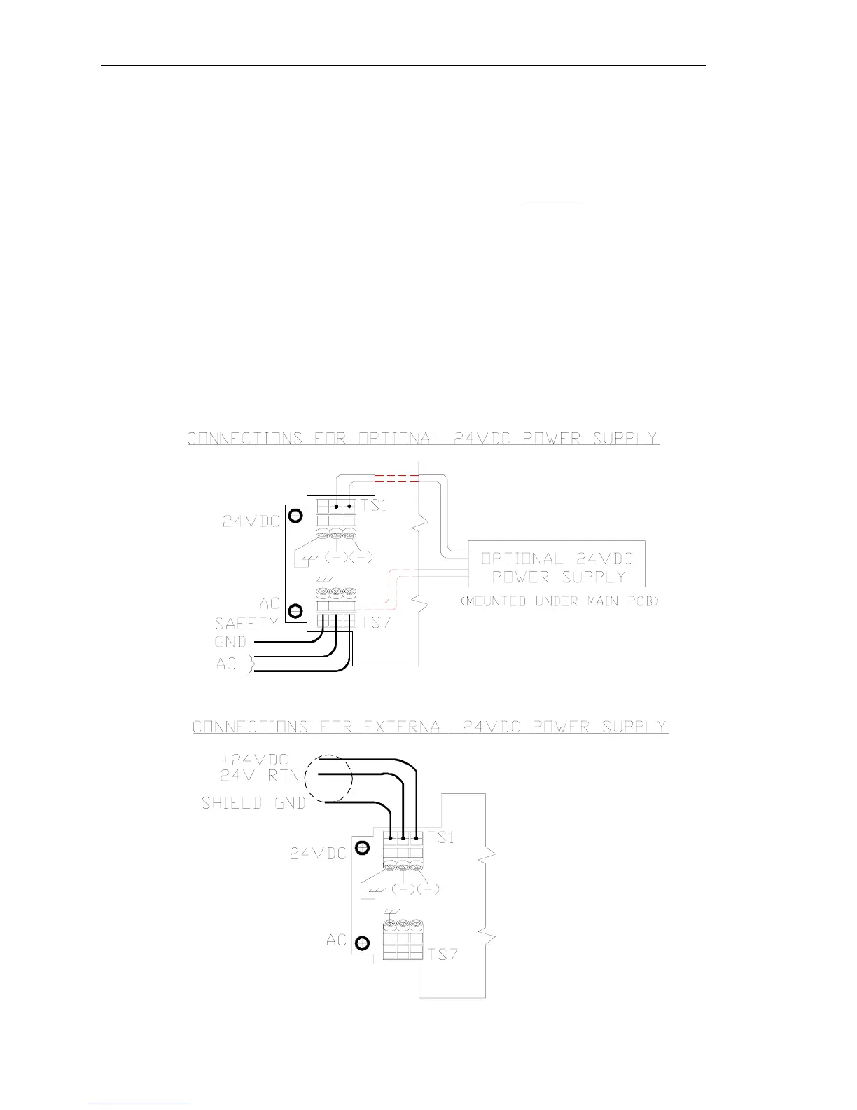
3.2.1. Power Input Wiring and Grounding
If the optional AC power supply is supplied by FOX, the input power can be 85 to 250 VAC. If the
customer supplies an external power supply, it must supply 24 VDC +/- 10 %, with a minimum of one
amp.
The enclosure must be properly grounded with a quality earth ground to protect the electronics from
static discharges. It is recommended that 16 gauge, stranded wire be used.
Figure 3-2 Power Input Wiring
Fox Thermal Instruments Inc., 399 Reservation Road, Marina, CA 93933 Page 17