Model FT2 101364
3. Start Up
3.1. Scope
This section describes the steps needed to get the FT2 Flowmeter running.
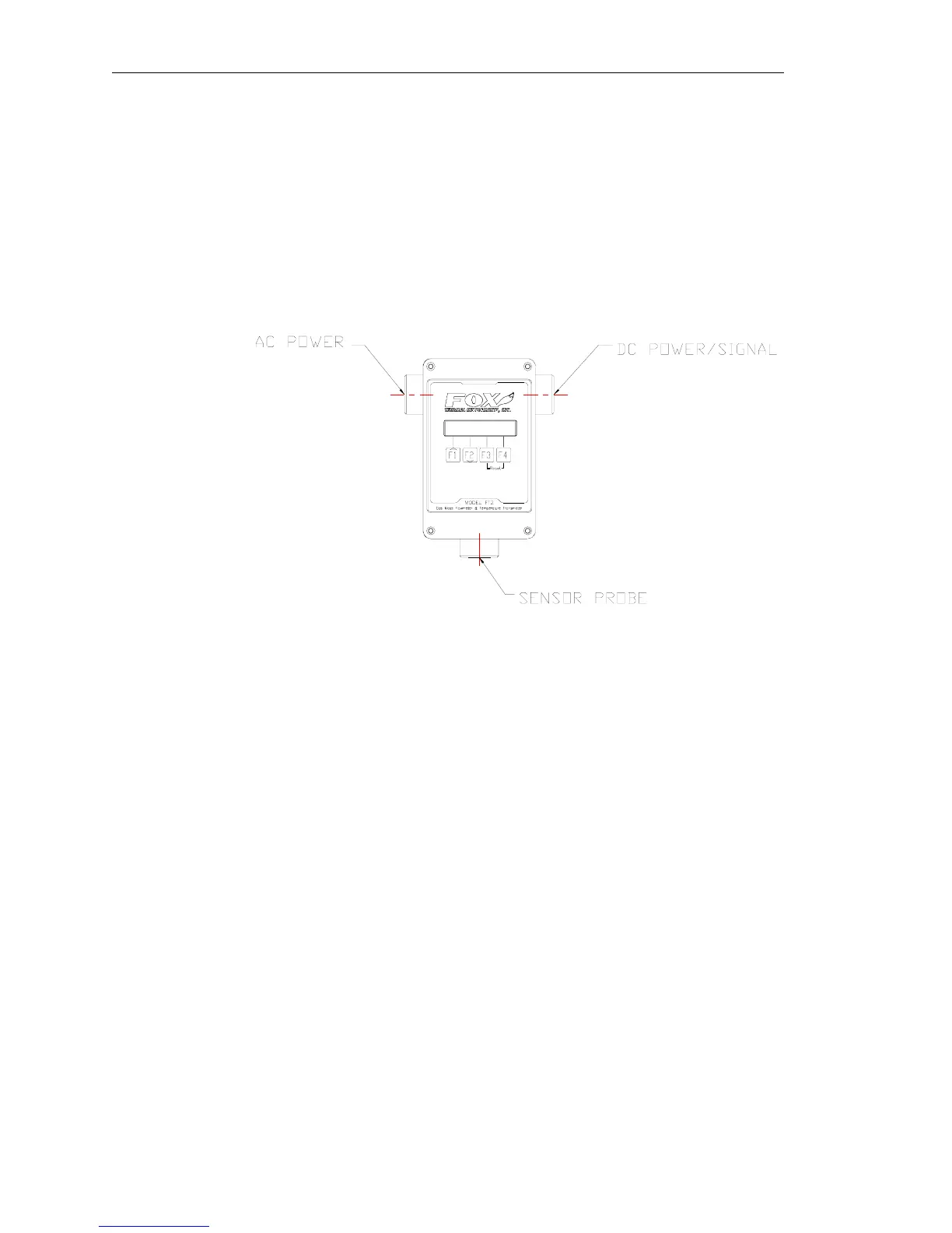
The enclosure has two separate conduit entries to maintain separation between AC input power and
output signal wiring. To eliminate the possibility of noise interference, use a separate cable entry for
AC power and signal lines.
Figure 3-1 Input Wiring
Note: All references to conduit orientation are from the Front Panel perspective.
3.2. Wiring
Warning! All installation procedures must be performed with power Off.
All plumbing and electrical installations of flow meters must be a combination of the end user’s best
engineering practices, in compliance with local codes, and the manufacturer’s recommendations.
• Do not install the FT2 enclosure near an igniter, igniter controller or switching equipment.
• Do not install an external power supply in a cabinet containing an igniter controller or switching
equipment.
• Do not power the power supply with an AC power source that is also used to power an igniter or
igniter controller.
Wiring Installation
Warning! This flowmeter contains components that can be damaged by static electricity. You
must discharge yourself by touching a grounded steel pipe or other grounded steel material prior
to working inside this flowmeter.
Wiring is accomplished by loosing the 4 captive screws holding the cover of the enclosure to expose
the electronic circuit boards. Bring customer supplied wires into the enclosure through the conduit
access on the sides of the enclosure. Cut wires for a 2-inch service loop. Use stranded copper wire, no
larger than 16-gauge. If you are using the optional AC power supply, connect the two AC wires and
the safety ground to the TS7 connector marked as AC (bring AC wires in through the left-hand conduit
hub). If an external 24 VDC power source is used, it is recommended that a twisted shielded pair cable
Page 16 Fox Thermal Instruments, Inc., 399 Reservation Road, Marina, CA 93933