101364 Model FT2
1.4. Analog 4-20 mA outputs
Two industry standard 4-20 mA isolated analog outputs are available to monitor flow rate and
temperature. Each output is scalable for the 4 and 20 mA values. See the programming section for
details.
1.5. Discrete I/O
One discrete input is available for remote resetting of the totalizer and elapsed time.
One isolated discrete output is available for generating an alarm for High or Low limits for temperature
or flow rate, if the output is not used for the pulse output.
1.6. Frequency/Alarm Output
One isolated frequency output is available to monitor flow rate and is typically used for totalization.
The maximum frequency output is 100 Hz. The output can be scaled by using the flow setting and
maximum frequency or using the pulse per unit or unit per pulse method of entry. The isolated digital
output can be used either as a frequency output or an alarm output but not both. The output type is
selected by JP1.
1.7. Local Display Options
An optional front panel with a LCD display and keypad is available to display measured data and
allow field programming of the flowmeter. The display is an easy to read, two-lines, 16 characters
backlit LCD and 4 function keys. The local display/keypad module is wired to the FT2 electronics
through connector TS6. TS6 is on the main board. Refer to the Programming section for a detailed
explanation of its usage.
1.8. Communication Features
The FT2 offers a RS232 serial link that communicates to a Palm™ PDA handheld or with a PC
application for data display and programming. Also, RS485 is available to connect to the optional
front panel with an interface to a specific bus converter (Profibus, DeviceNet or Ethernet). The RS485
can connect directly as an optional Modbus interface. Only one bus protocol is supported at one time.
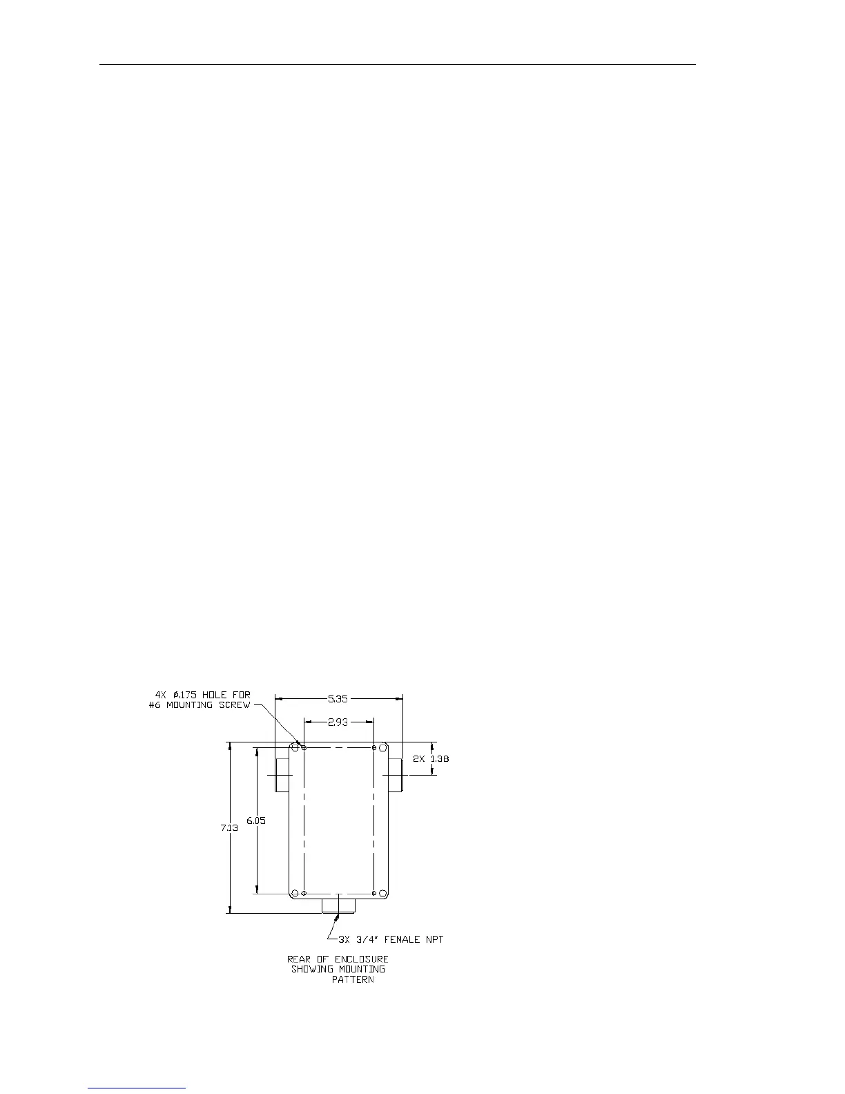
1.9. Dimension Details
Figure 1-2 Enclosure Mounting Dimensions
Rear View of enclosure without sensor or
conduit. AC power enters on one side, DC
power and signals enter on the other side.
Fox Thermal Instruments Inc., 399 Reservation Road, Marina, CA 93933 Page 5