101364 Model FT2
2.2.2. Installation Depth
Note: Some flowmeters are shipped with sensors that have equal length elements (see Figure 2-2).
Others are shipped with the sensor elements that are offset (see Figure 2-3). The sensor type supplied
was selected at the factory to be the best suited for your application. Follow the appropriate sensor
orientation instructions below. (Refer to Figure 1-5)
a. Install the compression fitting into the ¾-inch female NPT half coupling.
b. When installing in a 2-inch pipe or larger, install the end of the probe 0.87-inch past the
centerline of the pipe and tighten the compression fitting nut. Refer to Figure 2-1.
c. When installing into a 1½-inch pipe carefully install the probe into the pipe until it touches the
opposite wall and pull back 0.1-inch. Tighten the compression fitting nut.
Caution: Once the compression fitting is locked onto the probe, the probe can be removed or
rotated, but the insertion depth is locked in place.
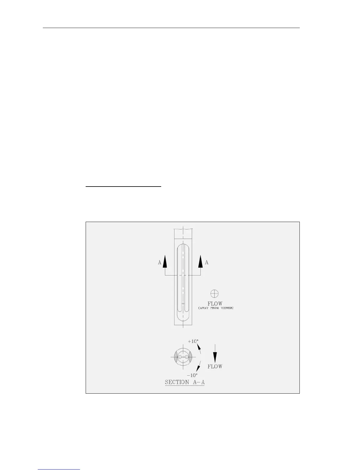
2.2.3. Sensor Orientation
Equal length sensor elements:
Install flowmeter with both sensor elements facing the flow stream within +/-10 degree.
Figure 2-2. Equal Length Sensor Elements.
Fox Thermal Instruments Inc., 399 Reservation Road, Marina, CA 93933 Page 11