101364 Model FT2
3.2.7. Remote Wiring Installation
Note: Remote wiring is only required when the Remote Electronics options is provided.
Five wire shielded cable required. The shielded cable should be ran through a separate grounded steel
conduit. (No other cables or wires in the conduit.)
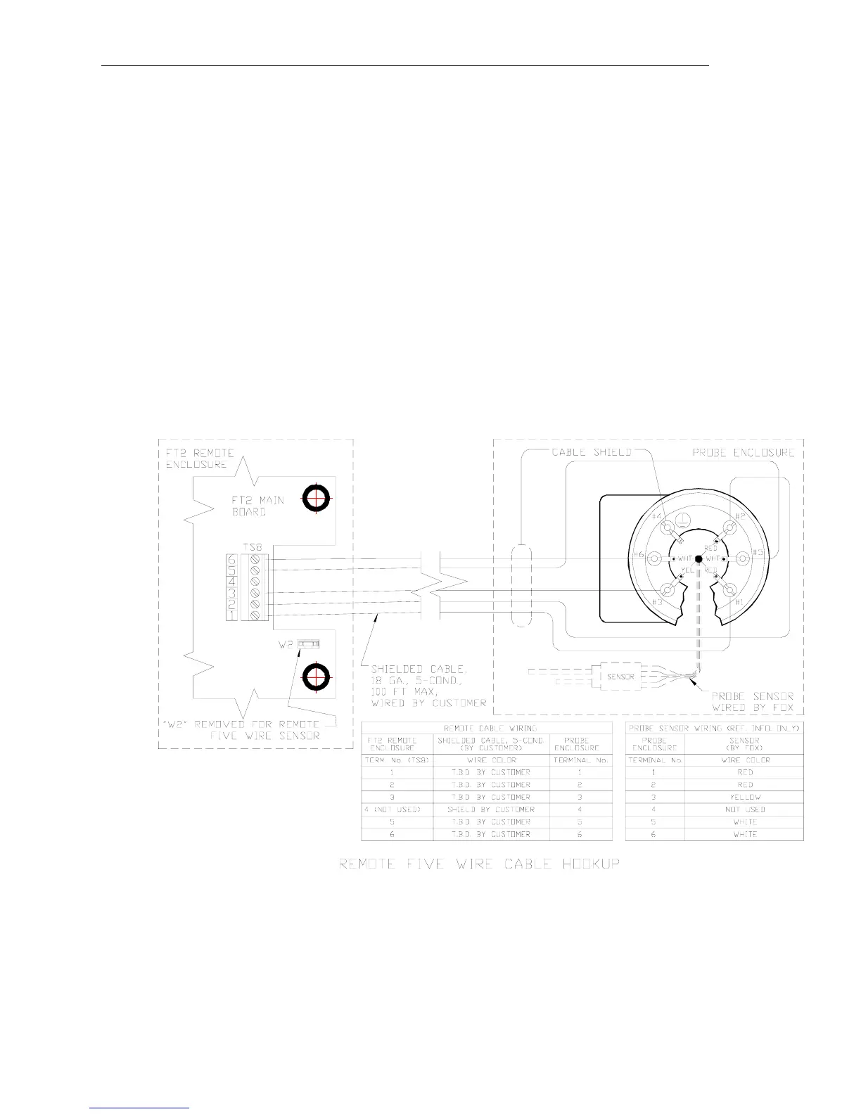
Connect sensor wires as follows: Red wires to terminals # 1 and # 2, white wires to # 5 and # 6 and
yellow wire to # 3, cable shield to # 4 (see Figure 3-8).
Connect other end to connector TS8 (see Figure 3-7) on the main FT2 board as follows:
Red wires to TS8 pin 1 & 2, white wires to TS8 pins 5 & 6 and yellow wire to TS8 pin 3.
If you are using your own cable, make sure that the cable does not exceed 100 feet and has a wire
resistance that does not exceed one ohm (18 AWG recommended). Do not connect the shield at the
FT2 enclosure end. On the FT2 board, make sure that the jumper W2 is not across both pins when a
5-wire sensor is supplied (see Figure3-8).
Figure 3-8 Sensor Wiring (5 wire) (see also Figure 1-6)
Fox Thermal Instruments Inc., 399 Reservation Road, Marina, CA 93933 Page 23