Model FT2 101364
2.2.5. Flowmeter Placement - Flow Body Style
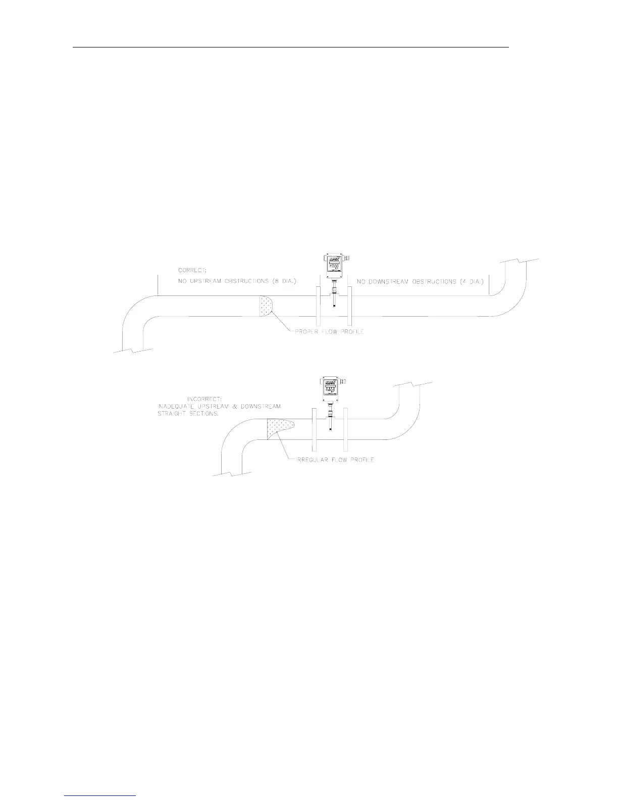
Install the Model FT2 Inline style flowmeter so that it is far enough away from bends in the pipe,
obstructions, or changes in line sizes to ensure a consistent flow profile. Eight diameters of
straight pipe upstream and four downstream are recommended.
The Model FT2 is welded, threaded or flanged to the customer’s pipe. Care should be taken to
ensure that the diameter of the mating pipe is the same diameter as the Model FT2 flow body or
errors in flow readings can occur. Installation procedure should be a combination of the end
user’s best engineering practices, in compliance with local codes, and the manufacturer’s
recommendations.
Figure 2-5 Flowmeter Placement - Flow Body Style
Page 14 Fox Thermal Instruments, Inc., 399 Reservation Road, Marina, CA 93933