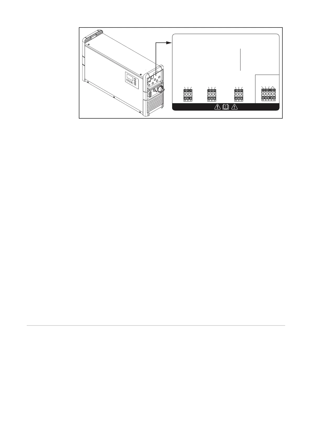
Risk of Electric Shock!
Do not operate at circuits
more than 250 V to ground!
0... 30V DC/4A
0... 250V AC/4A
Use Copper Conductors Only!
C Common
NC Normally Closed
NO Normally Opened
L Line
N Neutral Wire
max. 1A
AC Output!
42,0409,0008
C NC NO C NC NO C NC NO
L/C NC NO N
WARNING!
The optional relay board enables the charger's operating statuses and the con-
nected battery's state of charge to be evaluated externally. One or more external
consumers can also be supplied with L-N input voltage. A neutral conductor in
the electrical mains supply is a prerequisite for this. The configuration of the re-
lay board outputs is explained in the Operating Instructions for the charger: "Ad-
ditional functions" in the "Display" section.
More information on the relay board can be found in the instructions supplied
with the relay board option.
There follows an overview of the options that are directly connected with the re-
lay board. These relay-connected options are activated through the relay board
outputs:
-
Aquamatic control
-
Charging
-
Charge 50%
-
Charge 80%
-
Charge end
-
Main charge finished
-
Charge OK
-
Charging not finished
Signal if the battery is prematurely disconnected from the charger
-
Common error
-
Common error + warning
-
Signal lamp
-
Immobiliser device
-
ON
-
Refill indicator
-
Battery cooled
-
External air pump (electrolyte circulation)
Aquamatic con-
trol
The Aquamatic control contains the controller for a solenoid valve that automat-
ically tops up the water in the battery to be charged.
Standard setting
-
At the start of the recharging phase, the solenoid valve opens for 12 seconds
and then closes for 4 seconds.
-
This cycle is repeated 26 times.
USER setting
-
Configurable "ON" time (solenoid valve opens) after the end of the main
charge phase.
60