3
Fit ferrules to phase conductors and the ground conductor of the mains
cable; crimp ferrules with pliers
CAUTION!
Risk of short circuits!
If ferrules are not used, there is a risk of short circuits between the phase
conductors or between phase conductors and the ground conductor.
▶
Fit ferrules to all phase conductors and the ground conductor of the
stripped mains cable.
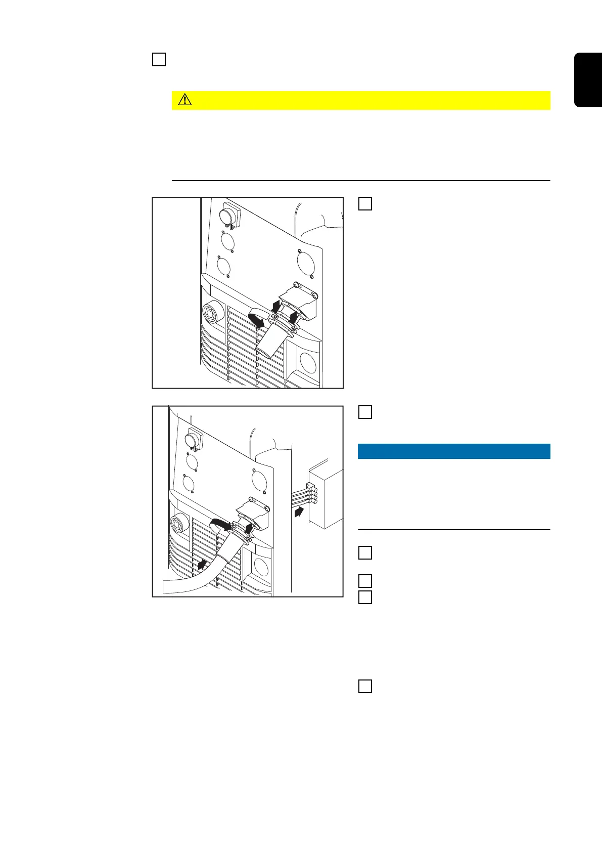
4
Undo the screws (2 x) and clamping
nut (size 30) on the strain-relief
device
5
Insert the mains cable into the
strain-relief device
NOTE!
Push the mains cable in far enough to
make it possible to connect the
ground conductor and the phase con-
ductors to the block terminal prop-
erly.
6
Tighten the clamping nut (size 30
mm)
7
Tighten the screws (2 x)
8
Connect the mains cable to the
block terminal correctly:
-
Ground conductor (green, or
green with yellow stripes) to
the PE connection
-
Phase conductors to connec-
tions L1 - L3
9
Re-fit the left side panel of the
power source
51
EN
 Loading...


