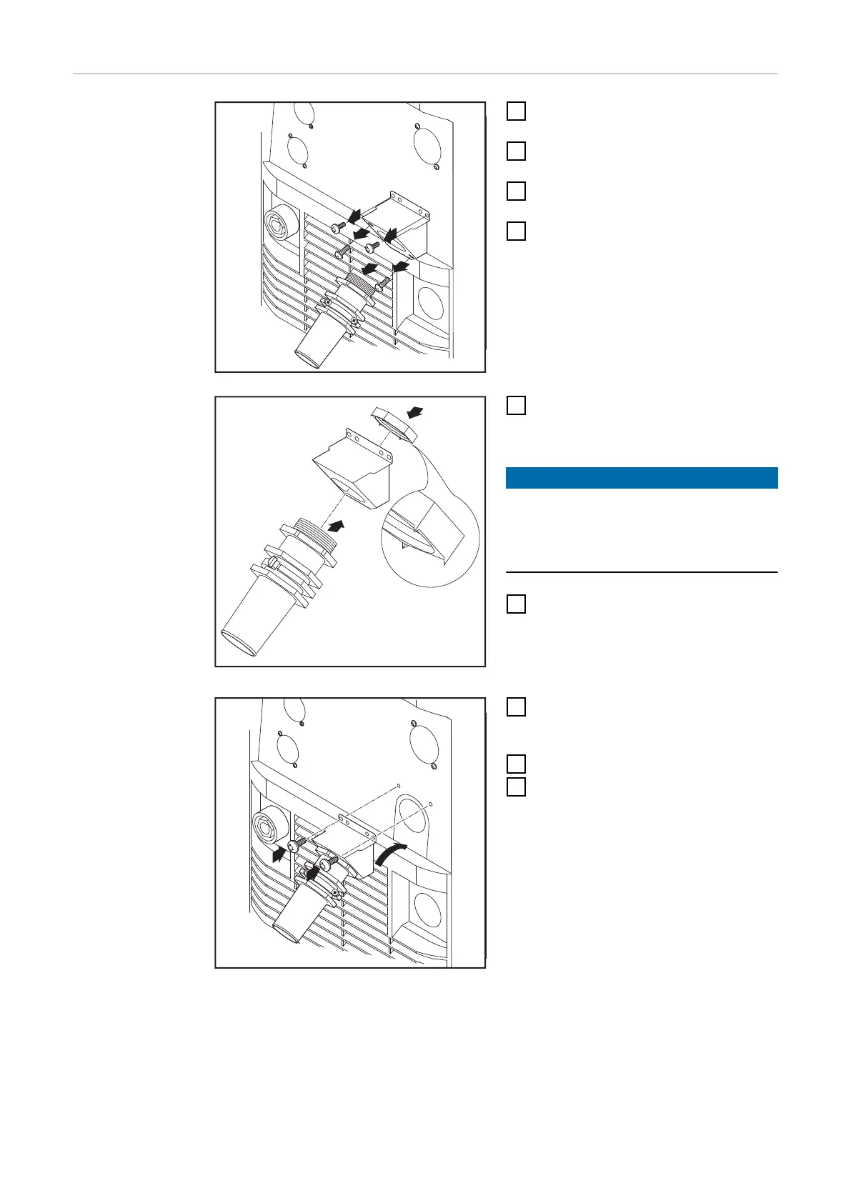
Replacing the
strain-relief
device
1
Remove the left side panel of the
power source
2
Remove the screws (2 x) from the
existing strain-relief device
3
Pull the existing strain-relief
device forwards to detach it
4
Remove the screws for the adapter
plate, and remove the adapter
plate
5
Insert the hexagon nut (size 50
mm) into the holding plate
NOTE!
To ensure a reliable earth connection
to the housing of the power source,
the points on the hexagon nut must be
facing the holding plate.
6
Screw the front of the large strain-
relief device into the hexagon nut
(size 50 mm). The hexagon nut
(size 50 mm) now bites into the
holding plate.
7
Slot the large strain-relief device
into the housing and fasten it with
2 screws
8
Connect the mains cable
9
Re-fit the left side panel of the
power source
52