2-8
CE Standard
Required airflow for the combustion air supply is 2m
3
/h per kW.
1. Connect the quick-disconnect hose to the fryer quick-disconnect under the fryer and to the building
gas line.
NOTE: Some fryers are configured for a rigid connection to the gas supply line. These units are
connected to the gas supply line at the rear of the unit.
When using thread compound, use very small amounts on male threads only. Use a pipe thread
compound that is not affected by the chemical action of LP gases (Loctite™ PST56765 Sealant is one
such compound). DO NOT apply compound to the first two threads. Doing so may allow some of
the compound to enter the gas stream, resulting in clogging of burner orifices and/or the control
valve.
2. Open the gas supply to the fryer and check all piping, fittings, and gas connections for leaks. A soap
solution should be used for this purpose.
3. Plug in the fryer to ensure the fryer drain valve is closed and fill the frypot with water or oil to the
bottom OIL LEVEL line at the rear of the frypot. Light the fryer described in the “Lighting
Instructions” topics found in Chapter 3 of this manual.
DANGER
“Dry-firing” your unit will cause damage to the frypot and can cause a fire. Always ensure that
cooking oil or water is in the frypot before firing your unit.
4. The burner manifold pressure should be checked with a manometer at this time by the local gas
company or an authorized service agent.
5. Check the rating plate for specific manifold gas pressures.
6. Confirm that the arrow forged into the bottom of the regulator body, which indicates gas flow direction, is
pointed downstream towards the fryers. The air vent cap is also part of the regulator and should not be
removed. If a vent line from the gas pressure regulator is used, it should be installed in accordance with lo-
cal codes or in the absence of local codes, with the National Fuel Gas Code, ANSI Z223.1- (latest edition) in
the U.S. and appropriate national or European harmonized standards (EN) in the European Union.
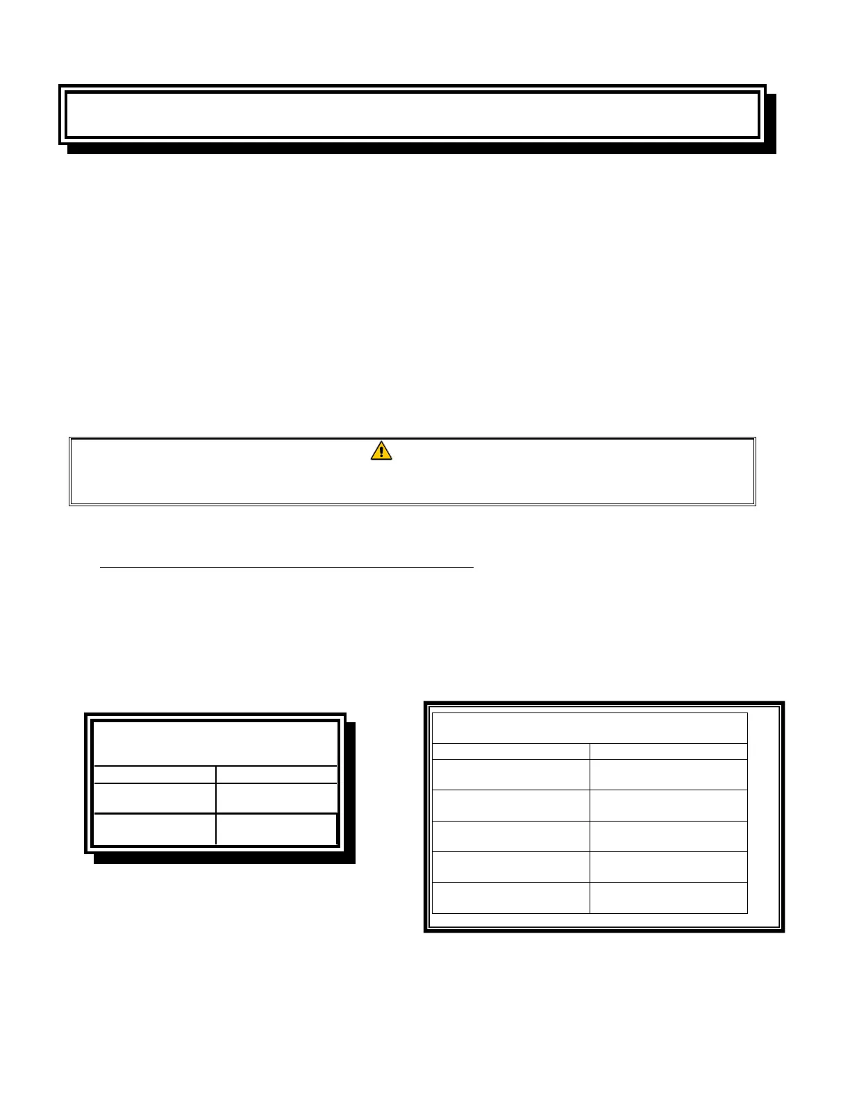
7. The tables list the burner manifold gas pressures for the various gas types that can be used with this
equipment.
Non-CE Standard
Burner Manifold Gas Pressures
Gas Pressure
Natural
3.20" W.C.
0.80 kPa
Propane
8.25" W.C.
2.5 kPa
CE Standard
Burner Manifold Gas Pressures
Gas Pressure (mbar)
Natural Gas Lacq
(G20) under 20 mbar
7
Natural Gas Gronique *
(G25) under 25 mbar
10
Natural Gas Gronique
(G25) under 20 mbar
10
Butane/Propane
(G30) at 28/30 or 50 mbar
17
Propane
(G31) under 37 or 50 mbar
20.6