1-25
LEFT VAT
IGNITION
MODULE
LED2 (PWR)
PWR
V2D
HIGH
LIMIT
SWITCH
LED1 (GV)
GAS
VALVE
IGNITION
MODULE
PWR
V1D
HIGH
LIMIT
SWITCH
GAS
VALVE
24V
TRANSFORMER
LED 5 (GV)
J1 PIN 9 J3 PIN 9
RIGHT VAT
J3 PIN 8
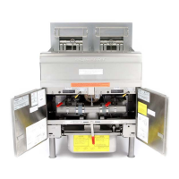
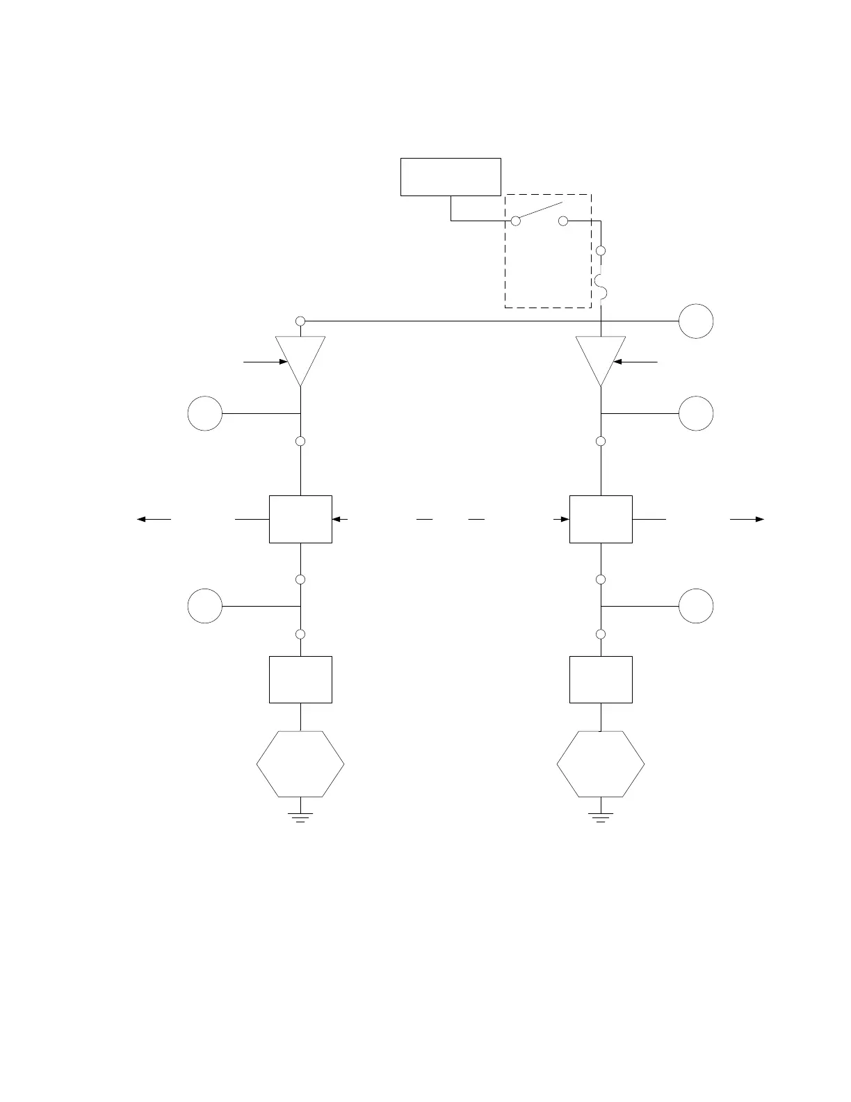
24 VOLT CIRCUIT
With Interface Board 106-6706 and
Two 807-3365 (DV) Ignition Modules
LED 4 (PWR)
High Voltage
to Ignitor
High Voltage
to Ignitor
Flame Sensor Flame Sensor
Heat Relay
(K3 Replaceable)
Heat Relay
(K2 Replaceable)
LED 3 (24V)
FUSE
Optional
AIR
PRESSURE
SWITCH
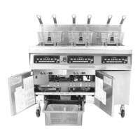
1.11.2 Troubleshooting the Gas Valve
Prior to checking for problems associated with the gas valve, ensure that the unit is calling for heat. Also, for
non-CE units, verify that the gas valve is in the ON position.
The following processes will assist you in troubleshooting the gas valve and ruling it out as a probable cause:
If 24 VAC is not present across gas valve main coil, the probable cause is the 24 VAC circuit. Refer to
the 24 VAC circuit troubleshooting guide.