3-2
Section 3 System Denition
3-2 System Conguration Denition
For MICREX-SX series SPF, register the actual unit conguration in the project.
3-2-1 System conguration denition
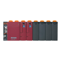
<Example of system conguration>
<System conguration denition tree screen>
The gure below shows the system conguration denition tree screen for the above system conguration.
<Rules for dening system conguration>
• In the system conguration denition, the unit on the right of the main unit is registered just below the main unit.
As for the unit station Nos. of units, the main unit is always assigned “0” (zero), and numbers beginning with 1 (one) are
assigned to Expansion right side units, in their connected order.
• The front board is connected on the front of the main unit and registered below the Expansion right side unit in the system
conguration denition. The unit station No. of the front board is xed to “100.”
• The Expansion left side unit is connected to the left of the main unit and registered at the lowermost location in the system
conguration denition. The unit station No. of the Expansion left side unit is xed to “200.”
Expansion
left side unit
Communication unit
Type: NA0LA-RS5
Expansion
right side unit
Digital input 8 points
Type: NA0E08X-3
Expansion
right side unit
Analog input 6ch
Type: NA0AX06-MR
Main unit with 40 points
Type: NA0PA40T-31C
Communication board
Type: NA3LA-RS1
 Loading...
