346 A Appendix
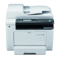
3. Loosen the two screws of the rear panel of
the printer and lift off the right cover.
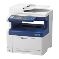
4. Loosen the two screws at the rear of the
printer and remove the dummy plate.
Note
• Do not completely remove the screws.
• Retain this dummy plate, because you will need to put
back the dummy plate after removing the parallel port
kit (optional).
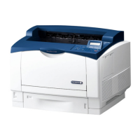
5. Aligning the Gigabit Ethernet Board Card
(with frame) and the controller board
connectors, insert the card from above.
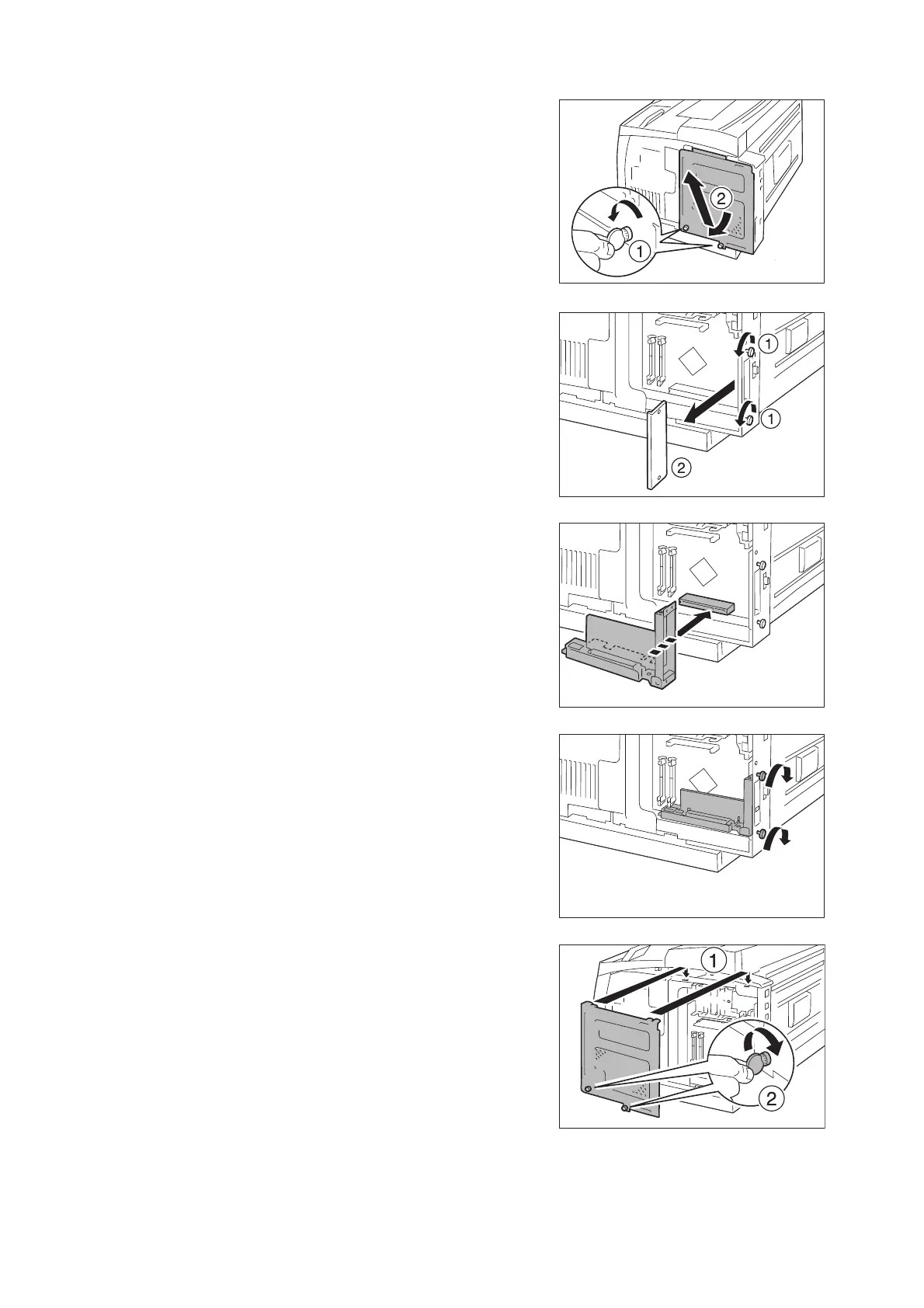
6. Secure the Gigabit Ethernet Board Card
from outside with the screws loosened in
step 4.
7. Insert the two tabs at the top of the internal
cover into the recess in the printer, and
close the cover.
Using a coin, etc., tighten the two screws at
the bottom of the cover.
 Loading...