44 2 Basic Operation
2 Basic Operation
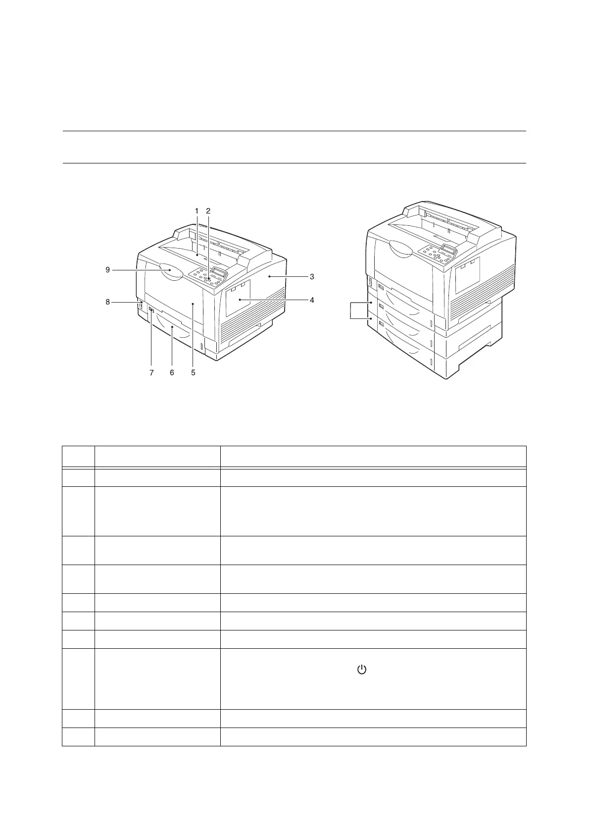
2.1 Main Components and Functions
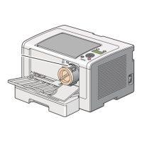
Main Unit
Note
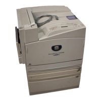
• The illustrations in this guide show the printer with the Duplex unit and 3 Tray Module installed.
10
Front and right side of views
No. Name Description
1 Center tray (standard) Delivers printed output face down here.
2 Control panel Switches the printer on/off.
Refer to
• “ Control Panel” (P. 47)
3 Right cover Remove this cover when installing the optional extension system memory or
parallel port kit (optional).
4 Accessory installation stand
mount
Remove this cover when installing the optional accessory installation stand
mount. The IC card reader can be placed on the accessory installation stand.
5 Bypass tray (standard) Open this cover to load paper.
6 Paper tray 1 (standard) Pull out this tray to load paper.
7 Size indicator Set here the label indicating the size of the paper set in the paper tray.
8 Power switch Switches the printer on/off. Press the < | > side of the power switch on the
printer to turn it on, and press the < > side to turn it off.
Refer to
• “2.2 Switching On/Off the Power” (P. 50)
9 Extension tray Pull out this tray when the printing paper is A4 portrait or larger than A4 size.
10 Paper trays 2 and 3 (optional) Up two trays identical to tray 1 can be added.
 Loading...